

QUICK START GUIDE
Page 12
© 2021 ABB. All rights reserved.
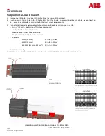
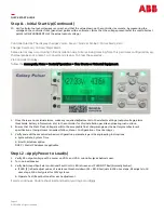
Step 11
-
Initial Start Up(Continued)
10.
Verify all plant output voltages are correct, and that the value shown on the controller is accurate, by measuring the
voltage on the controller front [panel test points with a voltmeter. (Note that the voltage presented at the controller test
points is ONE HUNDREDTH of the actual output voltage.)
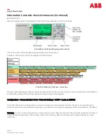
Controller Alarms: The display changes colors; Green = Normal, Amber = Minor Alarm, Red =
Charger Common/ Critical/ Major Alarm
Some alarms may occur during initial installation due to items being missing from this particular configuration; eg:
thermal probes not present, or Converters missing. To Clear these alarms:
Via Controller Display:
follow the menu path; Menu > Control/Operation > Clear Events or Uninstall Equipment.
1.
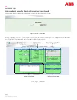
Once there are no residual alarms, make any required adjustments to the default settings (output voltage, alarm
thresholds, battery information, etc.) in the controller for this installation per site engineering instructions.
2.
Ensure that the Plant Float Voltage is within the acceptable float charge range per the battery manufacturer
’
s
specifications. If adjustment is needed, follow; Menu > Configuration > Float Settings >
3.
Verify and edit these controller basic configuration parameters per site engineering instructions.
a.
System Date, System Time
b.
Site ID, Site Description
DHCP / Static IP Address is applicable
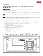
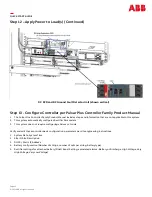
Step 12 –
Apply Power to Load(s)
1.
Verify DC output voltage with a meter on VDC+ and VDC–
controller jacks behind cover.
2.
Turn on load breaker.
3.
Verify No Ground Fault alarm—Ground Fault Unit U LED is Green and F LED NOT Red (Normally Amber).
a.
If LED [F] is Red, adjust values of resistance threshold down (R1 + R2). R1 adjusts in 10K ohm steps; R2 adjusts in 1K
ohm steps, 11K ohm typical for 125V systems.
b.
Operate Test/Reset button after each adjustment.
If alarm continues, trouble shoot load and battery wiring accordingly