


IM300 Intelligent Power Monitoring Instrument
40
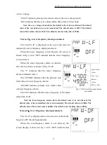
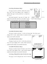
Fig 3-3-16 Low voltage alarm settings
page
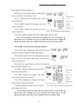
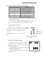
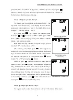
Fig 3-3-17 Lower frequency alarm
parameter settings page
.
S
creen 13
:
zero-current (low current) alarm parameters settings
The top of the screen displays "W-LC", the screen display and settings similar to
the twelfth screen.
Note: The limit value must be less than the return value.
S
creen 14
:
Over ground current alarm parameters settings
The top of the screen shows "W-ET", the screen display and settings similar
to the twelfth screen.
Note: The limit value must be more than the return value.
S
creen 15
:
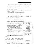
Low voltage alarm parameters settings
This page is used to set the low voltage alarm
parameters. The word "W-LV" is displayed at the
top of the screen, indicating the page is the low
voltage alarm parameters settings page, as shown in
fig. 3-3-16.
The allowed range of the alarm is 0 ~ 1, 0
means the alarm is not allowed, and 1 means the
alarm is allowed.
The limit value, the return value range is 0 ~
42kV; delay time range is 0.1 ~ 1800.0s;
Note: The limit value must be less than the return value.
S
creen 16
:
Over voltage alarm parameters settings
The top of the screen shows "W-OV", the screen
display and settings similar to the fifteenth screen.
Note: The limit value must be more than the
return value.
S
creen 17
:
Low frequency alarm parameters
settings
Summary of Contents for IM300 Series
Page 1: ...IM300 Operational Manual ...
Page 109: ...CNABB CNIIB IM300 201903 REV C ...


