


Operation Manual / 4 Product description / A100-M axial
2 Removal and installation / 2.3 Installing the turbocharger
© Copyright 2017 ABB. All rights reserved.
HZTL4033_DE
Revision B
December 2017
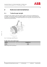
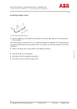
Removing auxiliary screws
Fig. 10: Removing auxiliary screw
u
Remove shipping screws (90334 / 90335) on the left and right side of the foot and place
in the toolbox.
The turbocharger is delivered with a pre-installed sliding block (68003). The shipping screws
secure the sliding block in the preset position. In operation, the foot can slip due to thermal
expansion.
u
Tighten clamping nuts as described in the following sections.
u
Connect all gas, air and oil pipes.
u
If present: Re-fit the insulation segments.
u
If present: Connect cable to speed sensor.
Page
13
/
99