


41-971.3M
Type HCB-1 Pilot Wire Relay System
12
The nominal 3-phase fault pick-up current from equa-
tion 7 is:
5.3.2. Ground Fault Pickup
Set R
0
= H
For line to ground fault:
5.3.3. Restraint Tap
Use maximum restraint tap.
6.0 INSTALLATION
The relays should be mounted on switchboard pan-
els or their equivalent in a location free from dirt,
moisture, excessive vibration, and heat. Mount the
relay vertically by means of the four mounting holes
on the flange for semi-flush mounting, or by means of
the rear mounting stud or studs for projection mount-
ing. Either a mounting stud or the mounting screws
may be utilized for grounding the relay. The electrical
connections may be made directly to the terminals by
means of screws for steel panel mounting or to the
terminal studs furnished with the relay for thick panel
mounting. The terminals stud may be easily removed
or inserted by locking two nuts on the stud and then
turning the proper nut with a wrench.
For detailed flexitest case information, refer to I.L.
41-076.
7.0 ACCEPTANCE TESTS
The following tests are recommended when the relay
is received from the factory.
HCB-1 current pickup values will be within 5% toler-
ance of the I.L. specification, only for those taps at
which the relay is calibrated. For other tap settings,
the tolerance may be higher than 5% of nominal,
unless recalibration of the relay is performed.
The HCB-1 is factory calibrated at the following taps:
R
1
: “C” Tap
R
0
: “H” Tap
T
“4” Amps
If other tap settings are used, the HCB-1 relay must
be recalibrated at the applied settings to obtain
pickup current within 5% of the I.L. specifications.
7.1.
MAIN UNIT
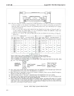
Connect the relay to the insulating transformer as
shown in Figure 8, and set C, H, 4 and maximum
restraint tap. With the insulating transformer termi-
nals H1 and H4 open circuited, measure the mini-
mum pick-up current I79 (min.), with current applied
through terminals 7 and 9. This value should not be
greater than 2.25 amperes.
NOTE: The relay may operate at values of cur-
rent lower than 2.25 amperes depending
upon the insulating transformer used and
the prior history of the polar unit. The
pickup should not be lower than 1.4
amperes. To increase pickup, short H1-H4
of insulating transformer, apply 40
amperes momentarily to terminals 3 and
5 of relay and check pickup of relay. It
should be 2.12 + 5% amperes. If not, the
polar unit should be recalibrated per
“Polar Unit Calibration.”
Now, connect a resistance, R
PW
, across H1 and H4
of the insulating transformer, with a 10-mfd capacitor
connected between H2 and H3. Connect a capacitor.
CPW in parallel with R
PW
. With R
PW
and C
PW
set as
specified in Table 5 suddenly apply I35 = 30 amperes
(through terminals 3 and 5).
I
nom
2
T
8 amperes
=
=
I
g
400
285
+
2
------------------------
5
600
---------
×
2.85
A
=
=
I
nom
2
0.12
4
×
×
0.96
A
=
=
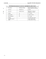
Table 5
RPW TEST - Maximum Restraint Tap
R1 = C, R0 = H, T-4
Insulating
Transformer
Ratio
R
PW
*
In Ohms
C
PW
in
Microfarads
4 to 1
6 to 1
1200
1900
2700
4300
0.75
0.33
Summary of Contents for HCB-1
Page 19: ...Type HCB 1 Pilot Wire Relay System 41 971 3M 19 THIS SPACE RESERVED FOR NOTES ...
Page 21: ...Type HCB 1 Pilot Wire Relay System 41 971 3M 21 ...
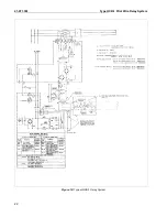
Page 22: ...41 971 3M Type HCB 1 Pilot Wire Relay System 22 Figure 10 Typical HCB 1 Relay System ...
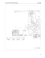
Page 23: ...Type HCB 1 Pilot Wire Relay System 41 971 3M 23 Sub 15 4810D98 ...
Page 27: ...Type HCB 1 Pilot Wire Relay System 41 971 3M 27 THIS PAGE RESERVED FOR NOTES ...