


26
Electro-pneumatic positioner TZIDC
41/18-79 EN
3.4 Commissioning
3.4.1 Commissioning procedure
1. Turn on the air supply to the positioner.
2. Turn on the electrical power supply to the positioner.
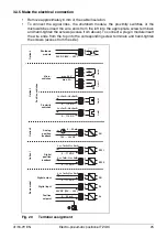
Apply the 4...20 mA signal to the analog input (ter11/-12).
3. Check for proper mounting:
-
Press and hold
MODE
; additionally briefly press or until mode 1.3 (manual
adjustment within sensor range) is indicated, then release
MODE
.
-
Press or to move the actuator to its mechanical limit stops in both directions,
and note the values. The angle of rotation is indicated in degrees.
For quick motion: Press and together.
Recommended range:
between -28° and +28° for linear actuators
between -57° and +57° for rotary actuators
Minimum angle: 25°
4. Run the standard autoadjustment function.
Note:
The standard autoadjustment function is only available with software revision
level 2.XX and higher.
For linear actuators:
1
-
Press and hold
MODE
until ADJ_LIN is displayed, then release.
-
Press
MODE
again and hold it down until the countdown is finished.
-
Then release
MODE
.
Standard autoadjustment is started.
or
For rotary actuators:
1
-
Press and hold
ENTER
until ADJ_ROT is displayed, then release.
-
Press
ENTER
again and hold it down until the countdown is finished.
-
Then release
ENTER
.
Standard autoadjustment is started.
When the autoadjustment function is finished successfully, the parameter settings
are automatically saved and the positioner returns to operating mode 1.1.
If standard autoadjustment should fail, the procedure is automatically interrupted,
and an error code is indicated. In this case press and hold or for approx.
3 seconds. The positioner returns to mode 1.3 MAN_SENS (manual adjustment
within sensor range). Check the assembly for proper mounting and, if required, read-
just it. Repeat the standard autoadjustment function.
5. If required: Adjust the dead band and tolerance band
This step is only necessary for critical actuators, e.g. very small ones. Usually,
it can be skipped.
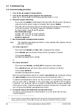
1.
The zero position is automatically determined and saved by the standard autoadjustment function:
turning counter-clockwise (CTCLOCKW) for linear and clockwise (CLOCKW) for rotary actuators.
Summary of Contents for HART Industrial IT enabled TZIDC
Page 38: ...38 Electro pneumatic positioner TZIDC 41 18 79 EN 5 Certificates ...
Page 39: ...41 18 79 EN Electro pneumatic positioner TZIDC 39 ...
Page 40: ...40 Electro pneumatic positioner TZIDC 41 18 79 EN ...
Page 41: ...41 18 79 EN Electro pneumatic positioner TZIDC 41 ...
Page 42: ...42 Electro pneumatic positioner TZIDC 41 18 79 EN ...
Page 43: ...41 18 79 EN Electro pneumatic positioner TZIDC 43 ...
Page 44: ...44 Electro pneumatic positioner TZIDC 41 18 79 EN ...
Page 45: ...41 18 79 EN Electro pneumatic positioner TZIDC 45 ...
Page 46: ...46 Electro pneumatic positioner TZIDC 41 18 79 EN ...
Page 47: ...41 18 79 EN Electro pneumatic positioner TZIDC 47 ...
Page 48: ...48 Electro pneumatic positioner TZIDC 41 18 79 EN ...
Page 49: ...41 18 79 EN Electro pneumatic positioner TZIDC 49 ...
Page 51: ...41 18 79 EN Electro pneumatic positioner TZIDC 51 ...
Page 52: ...52 Electro pneumatic positioner TZIDC 41 18 79 EN ...
Page 53: ...41 18 79 EN Electro pneumatic positioner TZIDC 53 ...
Page 61: ...41 18 79 EN Electro pneumatic positioner TZIDC 61 ...
Page 62: ...62 Electro pneumatic positioner TZIDC 41 18 79 EN ...
Page 63: ...41 18 79 EN Electro pneumatic positioner TZIDC 63 ...
Page 64: ...64 Electro pneumatic positioner TZIDC 41 18 79 EN ...


