ABB FSE-31 User Manual Download Page 24

24  Electrical installation        

Terminal designations

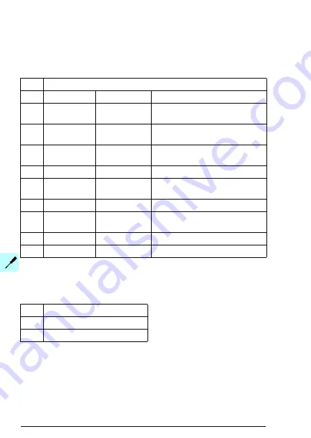
Pin allocation of the encoder interface connector 1 
(X31)

Pin allocation of the power supply connector


(X81)

X31

HTL

No.

Name

Specification Description

1

VCC_ENC_1

15 V DC

Encoder channel 1 power supply 
output

2

COM_ENC_1 0 V

Encoder channel 1 supply/signal 
common (ground)

3

A+_1

0…15 V DC 

Encoder channel 1 signal A+ 
input

4

A-_1

0…15 V DC 

Encoder channel 1 signal A- input

5

B+_1

0…15 V DC 

Encoder channel 1 signal B+ 
input

6

B-_1

0…15 V DC 

Encoder channel 1 signal B- input

7

Z+_1

0…15 V DC

Encoder channel 1 signal Z+ 
input

8

Z-_1

0…15 V DC

Encoder channel 1 signal Z- input

SHIELD_1

N/A

Encoder channel 1 cable shield

X81

Description

1/+

Supply voltage

2/-

Supply ground

Summary of Contents for FSE-31

Page 1: ... OPTIONS FOR ABB DRIVES FSE 31 pulse encoder interface module User s manual ...

Page 2: ...W hardware manual 3AXD50000020436 ACS880 37 160 to 3200 kW hardware manual 3AXD50000020437 ACS880 17 132 to 355 kW hardware manual 3AXD50000035158 ACS880 37 132 to 355 kW hardware manual 3AXD50000035159 ACS880 104 hardware manual 3AUA0000104271 ACS880 107 hardware manual 3AUA0000102519 Drive firmware manuals and guides ACS880 primary control program firmware manual 3AUA0000102519 Option manuals an...

Page 3: ...Commissioning User s manual FSE 31 pulse encoder interface module 1 Safety instructions Table of contents 4 Mechanical installation 5 Electrical installation 3AXD50000016597 Rev C EN EFFECTIVE 2020 06 05 ...

Page 4: ......

Page 5: ...s 12 Terms and abbreviations 13 Exclusion of liability 13 3 Hardware description Contents of this chapter 15 Product overview 15 Layout 17 Type designation label 18 4 Mechanical installation Contents of this chapter 19 Necessary tools and instructions 19 Unpacking and examining the delivery 19 Installing the module 20 5 Electrical installation Contents of this chapter 23 Warnings 23 Necessary tool...

Page 6: ...27 Commissioning test for FSE 31 28 7 Diagnostics Contents of this chapter 29 Faults and warning messages 29 LEDs 30 Safety encoder fault reaction 30 FSE 31 module replacement 30 8 Technical data Contents of this chapter 31 Dimension drawing 32 General data 32 Isolation areas 33 Encoder interface connector 1 X31 33 Power supply X81 33 Supported safety encoders 34 Supported encoder cables 34 Safety...

Page 7: ...h or damage can occur Read this chapter before you start the installation Use of warnings and notes Warnings tell you about conditions which can cause injury or death or damage to the equipment They also tell you how to prevent the danger Notes draw attention to a particular condition or fact or give information on a subject The manual uses these warning symbols Electricity warning tells you about...

Page 8: ...lation or maintenance work 1 Clearly identify the work location and equipment 2 Disconnect all possible voltage sources Make sure that re connection is not possible Lock out and tag out Open the main disconnecting device of the drive If you have a permanent magnet motor connected to the drive disconnect the motor from the drive with a safety switch or by other means Disconnect all dangerous extern...

Page 9: ...n the drive input power terminals L1 L2 L3 and the grounding PE busbar is close to 0 V Make sure that the voltage between the drive output terminals T1 U T2 V T3 W and the grounding PE busbar is close to 0 V 6 Install temporary grounding as required by the local regulations 7 Ask the person in control of the electrical installation work for a permit to work ...

Page 10: ...10 Safety instructions ...

Page 11: ...ce module is compatible with ACS880 primary control program version 2 21 or later It is recommended to always use the latest drive firmware FSO 21 safety functions module revision B or later Drive composer pro PC tool version 1 8 or later The supported safety encoder type is differential push pull HTL encoder Target audience This manual is intended for people who plan the installation install star...

Page 12: ...ount when building a safety system see FSO 21 safety functions module user s manual 3AXD50000015614 English WARNING User safety must be ensured by other means in all of the stages of the product s lifecycle when the safety option may not provide protection especially during commissioning system maintenance fault tracing and decommissioning Contents The manual consists of these chapters Safety inst...

Page 13: ...de and continue normal operation repair the possible fault and reboot the FSO module FEA 03 F series extension adapter module FSO 21 Safety functions adapter module which supports a safety encoder hi Z state A digital signal is neither driven to a logical high nor low level It is floating HTF Hardware fault tolerance EN IEC 62061 HTL High threshold logic Safety system Whole functional safety syste...

Page 14: ...The system integrator or other responsible party must make sure that the entire implementation complies with all relevant standards directives and local electrical code and that the system is tested verified and validated correctly ...

Page 15: ...also monitors the operation of the encoder and indicates faults to the FSO 21 module The FSE 31 module supports one HTL safety encoder The module has two built in encoder interface connectors X31 and X32 Only X31 can be used Interface X32 is reserved for future use and must be left unconnected The FSE 31 module needs an external 24 V DC power supply which must be connected to connector X81 For the...

Page 16: ...on specific parameters eg process safety time the required encoder resolution The operation environment of the FSE 31 module must comply with the specified conditions See FSO 21 safety functions module user s manual 3AXD50000015614 English If the FSE 31 module fails to operate replace it with a new one Do not try to repair the module For instructions on decommissioning the module see FSO 21 safety...

Page 17: ...Hardware description 17 Layout 6 7 3 4 1 2 1 5 X31 Pin no 1 2 3 4 5 6 7 8 9 ...

Page 18: ...r interface connector X32 reserved for future use 6 External power supply X81 7 Diagnostic LEDs Item Description 1 Type 2 Serial number of format RYWWSSSSWS where R component revision A B Y Last digit of the manufacturing year 4 5 for 2014 2015 WW Manufacturing week 01 02 for week 1 week 2 SSSS Integer starting every week from 0001 WS Manufacturing location 3 ABB MRP code of the FSE module 4 Combi...

Page 19: ...ls and instructions Torx screwdriver T10 For a complete list of tools see the applicable drive hardware manual Unpacking and examining the delivery 1 Open the option package 2 Make sure that the package contains FSE 31 pulse encoder interface module this manual not included if the module is installed into the drive at the factory 3 Make sure that there are no signs of damage ...

Page 20: ...ecautions on page 8 before you start the work 2 Pull out the lock 3 Put the module carefully into its position on the drive until the retaining clips lock it into position 4 Push in the lock 5 Tighten the mounting screw The maximum tightening torque is 0 8 N m 7 1 lbf in Note The mounting screw tightens the connections and grounds the module It is necessary for fulfilling the EMC requirements and ...

Page 21: ...Mechanical installation 21 5 3 4 2 ...

Page 22: ...22 Mechanical installation ...

Page 23: ...ter Safety instructions If you ignore the safety instructions injury or death can occur If you are not a qualified electrical professional do not do electrical work Necessary tools and instructions Slot head screwdriver 0 5 3 0 mm for encoder connectors Slot head screwdriver 0 4 2 0 mm for power connector Cabling tools For a complete list of tools see the applicable drive hardware manual ...

Page 24: ...2 COM_ENC_1 0 V Encoder channel 1 supply signal common ground 3 A _1 0 15 V DC Encoder channel 1 signal A input 4 A _1 0 15 V DC Encoder channel 1 signal A input 5 B _1 0 15 V DC Encoder channel 1 signal B input 6 B _1 0 15 V DC Encoder channel 1 signal B input 7 Z _1 0 15 V DC Encoder channel 1 signal Z input 8 Z _1 0 15 V DC Encoder channel 1 signal Z input 9 SHIELD_1 N A Encoder channel 1 cable...

Page 25: ... the FSO 21 module If there is no power or if the power is not sufficient FSE 31 remains in Safe state If this occurs when FSO is in running mode FSO will go into fail safe mode The safety encoder must be attached to the motor shaft according to the instructions of the encoder manufacturer FSE 31 does not detect mechanical failures outside of the encoder for example motor shaft slipping If an inte...

Page 26: ...r and 24 V DC for the module revisions A to E You can see the revision of the module on the type designation label Refer to Type designation label on page 18 4 Make sure that the electrical installation is completed See chapter Installation checklists in the FSO 21 safety functions module user s manual 3AXD50000015614 English WARNING Use only the X31 connector of the FSE 31 module to supply power ...

Page 27: ...f the drive the FSO 21 module and the FSE 31 module Required tools Drive composer pro PC tool version 1 8 or later Setting the parameters The FSE 31 module is taken into use by setting the relevant safety parameters of the FSO module using the Drive composer pro PC tool Validation of the safety system See the validation instructions in FSO 21 safety functions module user s manual 3AXD50000015614 E...

Page 28: ...the system design specification 4 Make sure that the installed encoder is suitable for the application and that the encoder is compatible with the FSE module See section Supported safety encoders on page 34 5 Make sure that the encoder is installed according to the instructions of the safety encoder manufacturer and according to the wiring instructions of this manual 6 For the encoder interface co...

Page 29: ...SE 31 module enters fail safe mode if any of these protections trip The module enters fail safe mode also if output voltages of the internal power supply are outside the specified limits due to power input overvoltage The FSE 31 module detects short circuits between the signal channels in the encoder cable For the fault and warning messages concerning the FSE 31 module and the safety encoder see t...

Page 30: ...SO 21 safety functions module user s manual 3AXD50000015614 English FSE 31 module replacement For instructions about replacing the FSE 31 module see FSO 21 safety functions module user s manual 3AXD50000015614 English Name Color Description PWR Green The module is powered up ENC STATUS Green The encoder is in normal operation Off An encoder fault is active STATUS Green The module is in normal oper...

Page 31: ...Technical data 31 8 Technical data Contents of this chapter This chapter contains the technical data of the module ...

Page 32: ... data Dimension drawing The dimensions are in millimeters and inches General data Degree of protection IP20 Ambient conditions Same as FSO 21 See FSO 21 safety functions module user s manual 3AXD50000015614 English ...

Page 33: ...ects the chassis to ground Encoder interface connector 1 X31 Connector pitch 5 0 mm wire size max 2 5 mm2 14 AWG Power supply X81 Connector pitch 3 5 mm wire size max 1 5 mm2 16 AWG 24 V DC tolerance 20 Maximum current consumption 500 mA SELV or PELV type power supply B A X81 X31 CHASSIS X1101 X32 Connection to the drive Power supply Encoder interface 1 Encoder interface 2 not in use Mounting scre...

Page 34: ...ted encoder cables Double shielded twisted pair cable Draka JAMAK 4 2 1 0 5 mm2 or equivalent The maximum cable length depends on the encoder type cable type and cable termination For more information see the encoder manufacturer s data Safety performance When the FSE 31 module and a safety encoder are used in a safety function with a SIL PL requirement the safety encoder must be SIL PL classified...

Page 35: ...00015614 English Related standards The FSE 31 and FSO 21 module combination complies with IEC 61508 ed 2 0 2010 IEC 62061 2015 Ed 1 2 EN 62061 2005 AC 2010 A1 2013 A2 2015 IEC 61800 5 2 2016 EN 61800 5 2 2007 EN ISO 13849 1 2015 Safety of machinery Safety related parts of control systems Part 1 General principles for design EN ISO 13849 2 2012 Safety of machinery Safety related parts of control sy...

Page 36: ...36 Technical data ...

Page 37: ...rvice contacts can be found by navigating to abb com searchchannels Product training For information on ABB product training navigate to new abb com service training Providing feedback on ABB manuals Your comments on our manuals are welcome Navigate to new abb com drives manuals feedback form Document library on the Internet You can find manuals and other product documents in PDF format on the Int...

Page 38: ...3AXD 50000016597 Rev C EN 2020 06 05 abb com drives Copyright 2020 ABB All rights reserved Specifications subject to change without notice ...

Reviews: