Overview
13
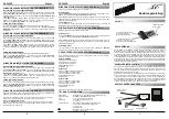
Figure 2. The construction of the Ethernet link and the FENA-01
Adapter module.
Ethernet connector X1
(see chapter
"Electrical
installation"
)
Diagnostic LEDs
(See chapter “Diagnostics”
in
appropriate Protocol Manual)
Ethernet
Node
ABB drive
Ethernet
Node
Hub, Switch or Router
Chassis Screw
(see chapter
"Electrical
installation"
)
Summary of Contents for FENA-01
Page 1: ...ABB Drives Hardware Manual Ethernet Adapter Module FENA 01...
Page 2: ......
Page 4: ......
Page 6: ...Safety instructions 6...
Page 16: ...Mechanical installation 16...
Page 18: ...Electrical installation 18...
Page 20: ...Definitions and abbreviations 20...
Page 23: ......