


E ZCLE A N
| CO M P R E SSED A I R SU P P LY U N I T | O I/E ZC L E A N - EN R E V. A
11
5 Configuration
NOTICE
• Schedule automatic cleans for configured probe(s)
only.
• Clean parameters are enabled only when the
Clean
Interval
is set (is not Off) – see "Configuration"
• Full software details are detailed in the transmitter
Operating instruction
(OI/AWT420-EN).
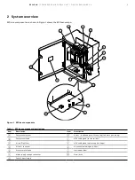
1
Ensure the probe to be cleaned is connected to the
transmitter.
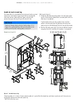
2
Ensure pneumatic connections are made between the
EZClean compressed air unit and an ABB compressed air
adaptor to be fitted on the sensor.
3
Ensure electrical connections are made between the EZClean
compressed air unit and the AWT420 transmitter – see
"Electrical connections" on page 10.
4
At the AWT420 transmitter, press the
key to display the
Operator Page
menu, then select Enter
Configuration
to
display the
Access Level
page.
Use the
key to select the
Advanced
menu item and press
the
key (below the
Select
prompt) to access Advanced
level menus.
Use the
/
keys to scroll to the
Input/Output
menu
and press the
key to enter the level. Scroll to the
Relay
menu using the
/
keys.
Configure Relay parameters for the associated probe as
follows:
– Set: Type to Output
– Set:
Source
to
Sx Clean
(where
x
corresponds to the
– sensor posit
io
n [1 to 2] at the EZLink connector)
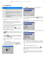
5
Exit the Input/Output menu and use the
/
keys to
scroll to the Sensor Setup menu:
Menu
Sensor Setup
Exit
Select
Press the
key – the
Sensor Setup
page is displayed:
1
2
3
Sensor Setup
S1 :DO
Salinity Units
Pressure Units
Back
Select
If more than 1 sensor is connected, select the required sensor
S1(to 2) :DO
(to be cleaned) and press the
key (below the
Select prompt).
The sensor
S1(to 2) :DO
menu page is displayed – see "Sensor
1
2
3
S1(to 2) :DO
Tag
PV Type
Units
Range High
Range Low
Filter Type
Back
Select
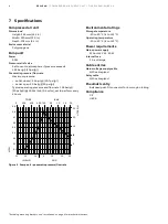
Scroll to the
Clean Interval
menu and set the required interval
between cleans.
1
2
3
Back
Select
S1(to 2) :DO
Clean Interval
Clean Type
Clean On Time
Clean Off Time
Number of Pulses
Recovery Time
Set the required clean parameters
(Clean Type / Clean On
Time / Clean Off Time* / Number of Pulses* / Recovery
Time / Clean Duration / Clean Output)
for the connected
probe.
*Enabled only if Clean
Type
is set to
Pulsed
.
When all required clean parameters are set, press the
key
repeatedly to exit the Sensor Setup level and return to the
Operator Page
.
The configured clean commences at the interval set after
this configuration is saved and repeats until re-configured or
stopped.