ABB EXGP Installation Manual Download Page 10

8

3.2.1

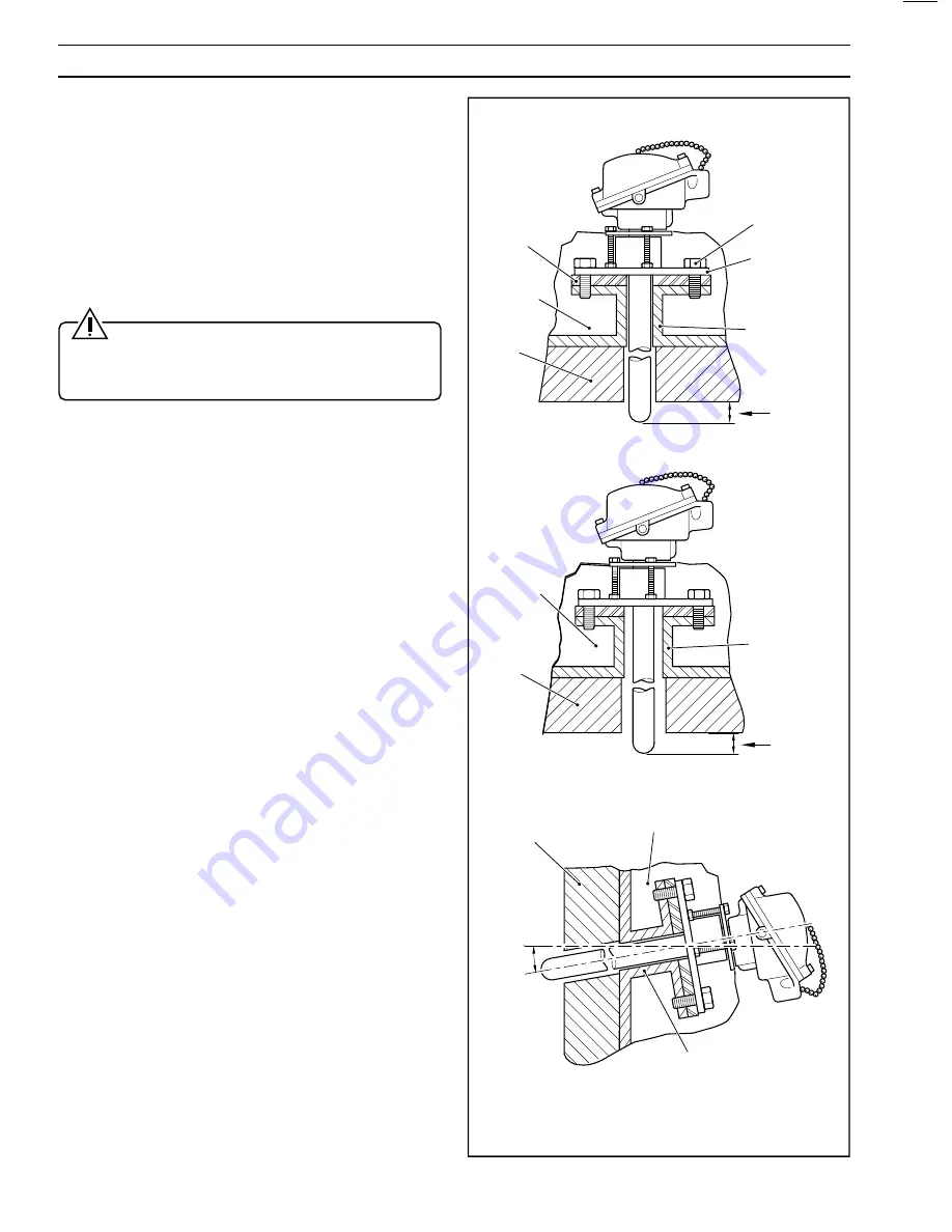
Mounting Configurations – Fig. 3.3

The probe may be fitted horizontally or, preferably, vertically
for prolonged high temperature operation.

Mount the probe through the furnace wall using the preferred
method shown in Fig. 3.3A. Ensure that a sufficiently large
hole is provided through the mounting – min. bore 1.65ins
(42mm) diameter – to avoid damage to the probe during
insertion or use.

Drill the fixing flange to suit the local fixing requirements before
assembling the probe – see Section 2.3.

Caution. To prevent furnace gas from

contaminating the reference air, always ensure that the
clamp ring, fixing flange and sealing ring are fitted to the
probe as described in Section 2.3.

With applications such as high temperature incinerators, fluid
bed boilers and ore roasters, where the level of water vapor in
the waste gases to be measured can be extremely high, it is
important that the mounting flange of the probe, including any
standoff which may be used, is thermally insulated to minimize
condensation within the probe – see Fig. 3.3A.

Condensation within the probe sheath, particularly in outdoor
installations, can be sufficient to allow water to come into
contact with the hot ceramic (zirconia) tube leading to thermal
shock and failure of the sensor. This problem is most likely to
occur on such installations where the plant is shut down
regularly over the weekend. Additionally, take care to protect
the head of the probe from the elements in outdoor
installations.

Raising the temperature of the probe as rapidly as possible
assists in reducing the level of condensation. This is not
possible on some processes where the plant temperature is
gradually raised to the normal operating level. The
temperature rise at the head of the probe can be assisted by
having a large clearance hole in the refractory allowing hot
gases to get up to the mounting flange/standoff – see Fig.
3.3B.

Horizontal installations are more likely to exhibit the problems
described. Where it is not possible to mount the probe in the
vertical position, install the probe with a slope of at least 10 to
15

°

 downwards from the head of the probe – see Fig. 3.3C.

Clamp Bolt

Fixing Flange

Support Tube
and Flange

5.90
(150) min.

Furnace
Wall

Thermal
Insulation

Packing

A – Standard Configuration

Support Tube
and Flange

Thermal
Insulation

Furnace
Wall

5.90
(150) min.

B – Improved Probe Heating

Support Tube
and Flange

Thermal
Insulation

Furnace Wall

10

°

 Min.

C – Inclined Configuration

Dimensions in inches (mm)

…3

INSTALLATION

Fig. 3.3 Probe Mounting

Summary of Contents for EXGP

Page 1: ...ABB Instrumentation EXGP Oxygen Analyzer System Installation Guide EXGP Probe ...

Page 2: ...program of innovative design and development to incorporate the latest technology The NAMAS Calibration Laboratory No 0255 is just one of the ten flow calibration plants operated by the Company and is indicative of ABB Instrumentation s dedication to quality and accuracy BS EN ISO 9001 St Neots U K Cert No Q5907 Stonehouse U K Cert No FM 21106 EN 29001 ISO 9001 Lenno Italy Cert No 9 90A Use of Ins...

Page 3: ...anical Installation Electrical Installation Part No IM EXGP INT TRANSMITTER Product Identification Mechanical Installation Electrical Connections Controls Displays Operation Programming Part No IM EXGP 4600 1 INTRODUCTION 1 INTRODUCTION 1 1 1 Documentation 1 1 2 Certification 1 1 3 System Hardware 2 2 PREPARATION 4 2 1 Unpacking 4 2 2 Checking the Code Number 4 2 3 Assembling the Probe 5 3 INSTALL...

Page 4: ...l that relates directly to oxygen concentration in the range 0 25 to 25 O2 over a process temperature range of 600 C to 1250 C An integral R type thermocouple provides accurate continuous measurement of the process temperature A calibration gas inlet port is provided to enable the probe to be checked using test gas mixtures without removing it from the process Reference air supplied at a rate of 1...

Page 5: ...ype Thermocouple mV Signal 0 to 1400 C Two 4 to 20mA Output Signals 0 to 1400 C and 0 25 to 25 O2 or 4680 Transmitter Mains Supply Flameproof Interface Electronics Unit EExd IIB T6 Conforming to BS5501 Part 5 1977 Flue 4685 Transmitter Retransmission Output Reference Air Line Entry Regulated Reference Air Unit 003000241 Mains Supply O2 mV Signal 20 to 180mV or or 1 INTRODUCTION Fig 1 2 System Sche...

Page 6: ...tached to it d Reassemble the packing and retain for future use 2 2 Checking the Code Number Fig 2 1 Before installing the equipment check the code number on the probe see Fig 2 1 Code No TEST GAS KEEP TIGHTLY CLOSED WHEN NOT IN USE Serial No AIR REF THC I P Remove cover retaining screws x3 Rotate cover Check probe code number against Table 2 1 1 2 3 e b o r P P G X E P G X E X X X 0 0 0 h t g n e...

Page 7: ... position at the end of the sheath ensuring correct orientation of the ring s center taper Locate the clamp ring over the 3 screws on the fixing flange and secure using nuts x3 Tighten the nuts down equally so that the fixing flange is pulled down tightly against the locating step on the sheath and the sealing ring is compressed until the adjacent faces of the clamp ring and sheath are 1 to 1 5mm ...

Page 8: ... in Fig 3 2 A clearance of at least 1in 25mm in excess of the overall probe length is necessary for installation or removal procedures Caution The probe must not be sited Where it would be subjected to mechanical or thermal shock In the presence of aggressive compounds e g molten slags molten silicates metals and vapors of lead zinc silicon and vanadium 1000 C Max Incoloy Sheath 1250 C Max Porcela...

Page 9: ...ntry Connector Head Mounting Flange 1 08 27 5 21 89 556 or 37 52 953 4 80 122 0 20 5 Probe Outer Sheath Fixing holes in mounting flange to be drilled by customer Dimensions in inches mm 4 92 125 4 53 115 3 46 88 3 INSTALLATION Fig 3 2 Overall Dimensions ...

Page 10: ...e into contact with the hot ceramic zirconia tube leading to thermal shock and failure of the sensor This problem is most likely to occur on such installations where the plant is shut down regularly over the weekend Additionally take care to protect the head of the probe from the elements in outdoor installations Raising the temperature of the probe as rapidly as possible assists in reducing the l...

Page 11: ...l requirements only e b o r P n o i t a c i f i c e p S d n a l G s l a n g i S e f a S y l l a c i s n i r t n I n o i t a c i f i c e p S e l b a C e c a f r e t n I n o i t a c i f i c e p S d n a l G d e i f i t r e c n o N 6 1 M l l a r e v o e r o c 2 2 0 6 1 t u p n I V m e l p u o c o m r e h T e p y T R 7 3 9 4 S B o t e l b a c g n i t a s n e p m o c e l p u o c o m r e h t e p y t R n ...

Page 12: ...ess to the interior of the probe head by unscrewing the lid fixing screws see Fig 4 1 b Remove the screwed plug from the test gas connector see Fig 4 1 c Fit 1 4in i d x 3 8in o d plastic or similar tubing and supply a test gas of known oxygen between 0 25 and 25 O2 concentration to the probe at a steady flow rate of 800 to 1000ml min Allow at least 5 minutes for the system to stabilize before mak...

Page 13: ...tc For the measurement of oxygen concentration it is necessary to correct for absolute temperature of the probe The temperature term in the Nernst equation on which the voltage output depends illustrates this point Nernst Equation E 0 0496 T log10 P0 P1 C mV Where T Absolute Temperature K P0 Partial Pressure Reference Gas P1 Partial Pressure Sample Gas C Cell Constant A2 Range of Operation Fig A1 ...

Page 14: ...12 NOTES ...

Page 15: ...ature I to P Converters and Field Indicators Flow Metering Magnetic Flowmeters Electromagnetic insertion type probes and watermeters Turbine Flowmeters Wedge Flow Elements Mass Flow Meters Transmitters sensors controllers and batch display units Level Control Submersible Capacitance Conductivity Pneumatic Instrumentation Transmitters Indicating Controllers Recording Controllers Customer Support AB...

Page 16: ...thout notice ABB 2000 Printed in UK 05 00 ABB Instrumentation Ltd St Neots Cambs England PE19 8EU Tel 44 0 1480 475321 Fax 44 0 1480 217948 ABB Automation Inc Instrumentation Division 125 E County Line Road Warminster PA 18974 USA Tel 1 215 674 6000 Fax 1 215 674 7183 ABB Instrumentation SpA 22016 Lenno Como Italy Tel 39 0 344 58111 Fax 39 0 344 58278 ...

Reviews: