


74 Electrical design and installation
Manual Energy Storage Inverter ESI-S
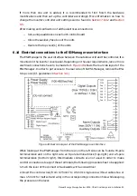
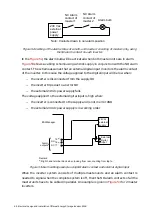
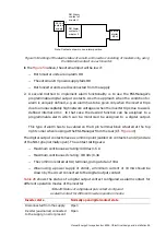
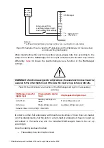
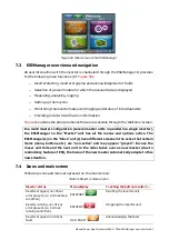
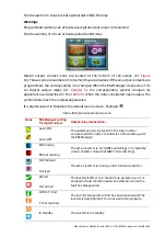
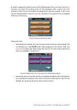
External switch for
switching between main
and auxiliary filter settings
24 Vdc
external
supply
+
-
3
(a)
4
(a)
ESI-Manager
Digital input 2
(15-24Vdc)
Remark:
(a)
Left hand terminal block when looking from rear, counting from top to bottom
Figure 55: Example of how to cable the 2
nd
digital input of the ESI-Manager for main/auxiliary
control switching functionality
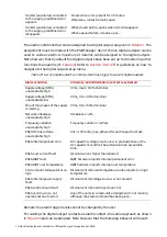
When implementing the function described above, please note that according to the
setup done with the ESI-Manager for the input considered, the inverter may behave
differently.
30 shows the inverter behavior as a function of the ESI-Manager
settings.
WARNING: If a function is assigned to a digital input, the same function must never be
assigned to the other digital input. Otherwise the inverter may behave erratically.
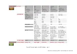
Table 30: Inverter behavior as a function of the ESI-Manager settings for main/auxiliary
switching
ESI-Manager setup for
digital input
Vlow applied to digital
input
Vhigh applied to digital input
Activ. Main
Auxiliary settings are
used
Main settings are used
Activ. Aux.
Main settings are used
Auxiliary settings are used
Remark: Vlow = 0 Vdc, Vhigh = 15-24 Vdc
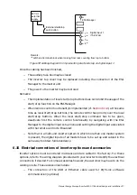
In order to obtain full redundancy with inverters consisting of more than one master
unit, the digital inputs of all the units in a multi-master arrangement have to be set up
and cabled in the same way and the individual ESI-Managers have to be set up
accordingly.
Once the cabling has been finished,
−
The auxiliary fuse box may be closed