


Manual Energy Storage Inverter ESI-S
Hardware description 19
−
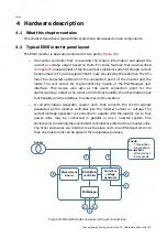
Interfacing to the IGBT-inverters;
−
The measurement of system voltages and currents for control, protection and
presentation purposes.
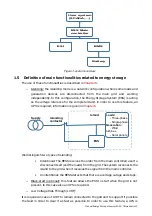
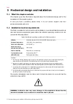
depicts the controller interface diagram of the ESI-S inverter.
Touch-screen
interface
ESI-
Manager
ESI main
controller
ESI Power
stage
Measurement
board
Modbus & PQ-
link interface
Programmable
Digital I/O
CT signals
3~ AC
out
DC out
(battery
connection)
ESI-
Manager
ESI main
controller
ESI Power
stage
Measurement
board
3~ AC
out
DC out
(battery
connection)
C
T
s
ig
n
a
ls
C
A
N
c
o
m
m
u
n
ic
a
ti
o
n
Interface to system
controller or to user
M
a
s
te
r
u
n
it
S
la
v
e
u
n
it
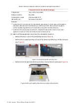
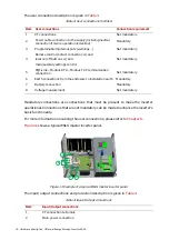
Figure 13: Controller interface diagram of the ESI-S
When the inverter consists of a master unit only, the customer has to:
−
Wire the CT signals (on a designated terminal) if required,
−
Connect the AC power lines (with or without neutral),
−
Connect the DC power line,
−
Connect the control of the DC contactor
−
Connect the voltage measurement and islanding contactor control if required
−
Set up the installation parameters and user’s requirements with the ESI-Manager.
He may also want to wire the communication interface (Modbus or Ethernet) and the
programmable digital I/O (e.g. alarm contact, remote control).
When a second unit is added, it is connected to the first enclosure by means of a CAN
bus communication link (1). In addition, the CT measurements have to be supplied to
each unit, e.g. through a daisy chain link with return path if power quality features are
used.
All units have their own AC-connection and main contactor protection.
All units have their own DC connection and DC contactor.