Manual Energy Storage Inverter ESI-S
Commissioning instructions 171
−
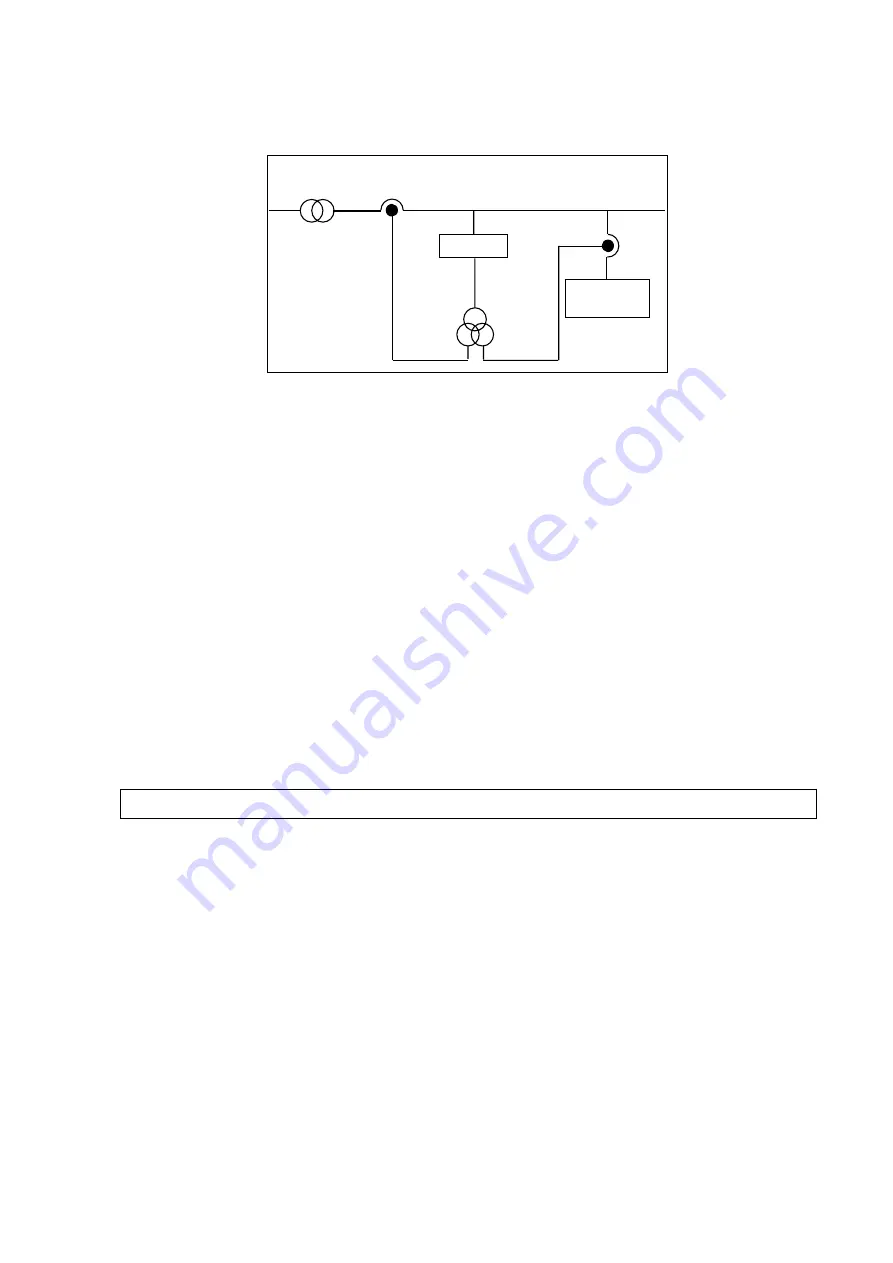
In installations where active inverters and passive inverters are present, the active
inverters must be installed downstream of the passive inverter. If this is not
possible, the CT connection scheme of
shall be used.
Feeding
transformer Filter CTs
Passive
filter
ESIx
+
-
Figure 91: CT connection guidelines for the case that a passive inverter is installed downstream
of the inverter
Further, when a passive inverter and an active inverter/ESS system are installed
on the same bus, it is not recommended to select on the active inverter the
harmonics at or below the tuning frequency of the passive inverter. If these
harmonics are selected, the SDP function may stop filtering these harmonics
temporarily resulting in a reduced overall filtering performance.
−
In installations where 2 non-compatible masters are connected to the same CT,
respect the following guidelines for best performance:
1. Select different harmonics on both units
2. If 1 above is not possible, put one inverter in Mode 1 and the other inverter in
Mode 3
Note: ‘Non-compatible’’ master units are master units that cannot or are not
interconnected with the RJ45-communication cable.
Please do not forget to fill in the commissioning report for future reference.
8.11 Commissioning report
The commissioning report is designed to help the person in charge of the
commissioning.
Before installation and operation of the ESI, read the relevant sections of the Instruction
Manual.


