4
1
1
10
8
7
6
5
9
2
2
3
3
DCB r e a k
– InstructIons for InstallatIon, servIce and maIntenance
4
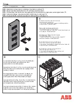
The operating principle of the DCBreak circuit
breaker is described below.
When the electromagnetic actuator (7) is energized,
the main lever (6) is first pushed forwards against
the latching lever (5) and then turns, allowing the
movable main contact (9) to advance until the circuit
breaker closes. After about one second, the current
required to keep the circuit breaker in the closed
position is limited to the "closed position holding
value" by limiting power consumption to about 5 W.
When the electromagnetic actuator (7) is de-
energized, its internal spring causes the main lever
(6) to return, thereby separating the main contacts
(9) until the circuit breaker reaches the open
position.
The rating plate (1) affixed to the side of the circuit
breaker shows the settings of the release device in
relation to the position of the adjustable screw (2).
The range of values is established during the routine
factory tests to which each circuit breaker produced
is subjected and cannot be used for any other circuit
breaker.
—
3. Operating principle
When the value of the current through the circuit
breaker exceeds the trip threshold setting in the
instantaneous overcurrent release, the current that
flows through the lower terminal (2) generates, by
means of the magnetic circuit (3), sufficient force to
overcome the corresponding latching force and to
lower the trip lever (5), thereby releasing it. Once the
trip lever (5) has been released, the return spring (8)
separates the main contacts (9) while the main lever
(6) meshes against the trip lever (5) again, ready for
the next closing operation. The arc generated
between the main contacts (9) runs along the arc
ramps (1) before being pushed upwards towards
the plates of the arc-quenching chute (10), where it
is interrupted.


