background image


QUICK START GUIDE


Page 5


© 2021 ABB. All rights reserved.


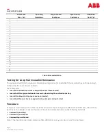
Loop Pair Insulation Resistance Testing


Adjust the meter to the ohms range and carefully connect the multimeter leads to the RING and TIP terminals for 
each cable pair connection. If any resistance is measured > 100K ohms, do not use for Line Power.


Adjust the meter to the ohms range and carefully connect the multimeter leads to the TIP and GROUND terminals 
for each cable pair connection. If any resistance is measured > 100K ohms, discard that pair


Adjust the meter to the ohms range and carefully connect the multimeter leads to the RING and GROUND terminals 
for each cable pair connection. If any resistance is measured > 100K ohms, do not use for Line Power.


Full System Test


Using a CP3200 to turn up the individual cable pairs, sequentially add line cards. After the insertion of each line 

card, confirm the 

Green Lights

” 

are illuminated as each circuit card is added. If any light show as 

RED

” 

move the 

card to a different circuit pair and tag that cable pair. Do not sign off on the site until all the circuits show 

GREEN

” 

for a full day.


Summary of Contents for CP3200

Page 1: ... test equipment will include the following Multi meter CP3200 190V Line Power System Test Procedure Perform the following steps for each cable pair Record the results in the table provided at the end of this document Testing will be performed in two manners These include testing for the presence of AC voltage on the open ended conductor pairs and testing for presence of dc voltage on cable pairs T...

Page 2: ... to proceed in using that cable pair Adjust the meter to read AC voltage and carefully connect the multimeter leads to the RING and TIP terminals for each cable pair connection If any AC voltage is measured note the level on Table 1 Adjust the meter to read AC voltage and carefully connect the multimeter leads to the RING and TIP terminals for each cable pair connection If any AC voltage is measur...

Page 3: ...proceed in using that cable pair Adjust the meter to read DC voltage and carefully connect the multimeter leads to the RING and TIP terminals for each cable pair connection If any DC voltage is measured record the data in Table 1 Adjust the meter to read DC voltage and carefully connect the multimeter leads to the TIP and GROUND terminals for each cable pair connection If any DC voltage is measure...

Page 4: ...nserted Insure that NO power has been applied to the cable pairs during this test AC Presence Pass Fail Tip to Ring Resistance Ring to Ground Resistance Tip to Ground Resistance CABLE Pair Pass Fail 1 2 3 4 5 6 7 8 9 10 11 12 13 14 15 16 17 18 19 20 21 22 23 24 25 Procedure Using your multi meter set for ohms resistance measurement IF any pair reads less than 100K ohm discard that pair For each ca...

Page 5: ... If any resistance is measured 100K ohms discard that pair Adjust the meter to the ohms range and carefully connect the multimeter leads to the RING and GROUND terminals for each cable pair connection If any resistance is measured 100K ohms do not use for Line Power Full System Test Using a CP3200 to turn up the individual cable pairs sequentially add line cards After the insertion of each line ca...

Page 6: ...QUICK START GUIDE Page 6 2021 ABB All rights reserved Notes ...

Page 7: ...QUICK START GUIDE Page 7 2021 ABB All rights reserved Notes ...

Page 8: ...ccept any responsibility whatsoever for potential errors or possible lack of information in this document We reserve all rights in this document and in the subject matter and illustrations contained therein Any reproduction disclosure to third parties or utilization of its contents in whole or in parts is forbidden without prior written consent of ABB Copyright 2021 ABB All rights reserved ABB 601...

Reviews: