


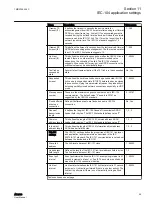


Name
Description
Value range
I frames TX
timeout (t1)
It defines the timeout in seconds the device waits for
acknowledgement from IEC-104 master after sending last I format
APDU or control frame (e.g. link test). If no acknowledgement is
received during the defined time the device will close the network
connection and the IEC-101 link. The t1 must be longer than the
network round-trip-time. The IEC-104 standard suggests 15
seconds.
1...255
I frames RX
timeout (t2)
This defines the timeout in seconds from the last received I format
APDU before sending acknowledgement. The t2 must be smaller
than t1. The IEC-104 standard suggests 10.
1...255
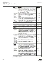
Link test
interval (t3)
This defines the interval in seconds how often the IEC-104 link is
tested if there is no other activity. The recommended value
depends on the criticality of the link. The IEC-104 standard
suggests 20 seconds but for pay-per-use GPRS connections the
practical value may be substantially longer.
1...65000
Test link on
suspended
state
Answer to test frame activation if the 101 link is in the suspended
state.
No, Yes
Suspended
timeout
This defines the time in seconds how long a connected IEC-104
link can be in suspended state (STOPD) before the device closes
the connection. Using this parameter increases the probability of
detecting partially closed network connections especially in UDP
mode.
1...65000
Max sequence
number
These are the maximum sequence number used in IEC-104
communication. The default value “0” equals to 32767 as
suggested by the IEC-104 standard.
0...32767
Flush buffered
events on
connection
Defines if buffered events are flushed on new a IEC-104
connection.
No, Yes
Cause of
transmission
length
It defines the length of IEC-104 Cause of transmission ASDU
header field in bytes. The IEC-104 standard defines value “2”.
1, 2, 3
Common
address length
This defines the length of IEC-104 Common address ASDU
header field in bytes. The IEC-104 standard defines value “2”.
1, 2, 3
Info object
address length
This defines the length of IEC-104 Information object address
ASDU header field in bytes.
1, 2, 3
IEC-101
settings
The IEC-101 settings define the properties of IEC-101 link layer
and application layer parameters as described in the IEC
60870-5-101 standard. The IEC-101 communication is carried out
between the device and a IEC-101.
Slave link
address
The link-level address of IEC-101 slave.
1...65000
Link address
field length
Defines the length of the IEC-101 link-level address field in bytes.
The link-level address of IEC-101 slave.
1, 2
Event poll
interval
Event poll interval defines the IEC-101 event polling interval in 0.1
second increments (class 1 or 2 poll). The events are polled only
when the IEC-104 connection is active.
1...65000
Link test
interval
Link test interval defines the IEC-101 link test interval in 0.1 second
increments. Link test is performed if there is no other activity. The
link test is performed if there is no other activity during defined
interval.
1...65000
Table continues on next page
1MRS758459 C
Section 11
IEC-104 application settings
ARC600
59
User Manual