


1SFC100008M0201 Nov 2018
4/4
ABB AB, Control Products
SE -721 61 Västerås, Sweden
Tel46 21 32 07 00
T46 21 12 60 01
http://www.abb.com/lowvoltage
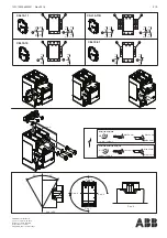
2,9 Nm - 26 lb.in
165
M5
35
187
M5
43,8
AF(S)190, AF(S)205
AF(S)265, AF(S)305, AF(S)370
General
a very wide voltage range.
Code-11…-14
Operation is done, as with conventional contactors, by applying and removing supply voltage on A1
and A2. Closing 85% and opening at 55% of the lower nominal voltage limit, which is indicated in the
functional diagram.
A1/A2
1
X5
2
3
A1 A2
ON
OFF_N
COM
96
0V
95
+24 V
When used with switches the wiring can be done
according to diagram above.
Contactor
Start
Stop
Supply voltage
Relay
Note: Emergency stop should disconnect A1 and A2
Position
Contactor
closed
Contactor
open
Supply
Functional diagram
vo
(A1/A2)
ltage
Low
High
Normal range
Operationalrange
85% of lower voltage range level
55% of lower voltage range level
1
0
1
0
High
Low
Closed
Open
ON
OFF_N
Voltage
Position
5
1
2
3
ON OFF_N COM
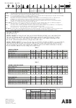
Code-33 and -34 built-in PLC interface
Operation is controlled by separate logic control signals from for instance a PLC. Use of logic control
requires a steady supply voltage on A1 and A2 within the rated voltage range, as described for
code-11…-14. The function of the logic control signal will no longer be guaranteed when the supply
voltage on A1 and A2 is removed.
The logic control signals are operated with 24V d.c. There are two control signals (ON and OFF_N) and a
common reference (COM). For the control signals, the function is guaranteed from 15V d.c. (6mA) to 33V
d.c. (20mA).
The contactor is closed by a control signal ON and opened by removal of control signal from OFF_N. The
functions are described in diagram below. “1” means 24V d.c. between the control signal and COM. “0”
means no voltage between the control signal and COM. Minimum control signal pulse length for
opening and closing is 10ms. To connect the PLC interface use cable dimension of max 1.5mm2.