On-Site Service Instructions
Document nbr
3AXD10000303478
ABB Oy, Drives Service
ACx580-01 R0-R5
Related to material
Department
Date
Revision
Page
ESP300
13.08.2018
F
39 (41)
© Copyright 2018 ABB Oy. All rights reserved. Specifications subject to change without notice.
3. Fault tracing
A possible fault in an output or an input bridge can be traced without opening the module. In this
section there are given pass criteria for following measurements conducted with a multimeter for
frame sizes R0-R5:
· Input bridge diode measurement from input connectors
· IGBT freewheeling diode measurement from output connectors
If a broken semiconductor module is detected, the whole drive must be replaced.
Note: Always make sure that there is no voltage connected to input terminals. In case a
permanent magnet motor is used, the motor axel must not rotate as it would feed voltage to
drive side.
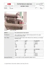
STEP 1
Input bridge diode measurement
Performance
Use a multimeter to make sure that the measurements for the input bridge
diodes are OK.
Pass criteria
By using the diode measurement setting for the multimeter, you should get
following values:
Note: In case of a controlled charging circuit, the input bridge
measurement is not possible for all phases.
+ probe
- probe
R1-R3 display
R4 display
R5 display
L1
+DC
~0,5 Vdc
~0,45 Vdc
~1,1 Vdc
L2
+DC
~0,5 Vdc
~0,45 Vdc
OL
L3
+DC
~0,5 Vdc
~0,45 Vdc
OL
+DC
L1
OL
OL
OL
+DC
L2
OL
OL
OL
+DC
L3
OL
OL
OL
+ probe
- probe
R1-R3 display
R4-R5 display
L1
-DC
OL
OL
L2
-DC
OL
OL
L3
-DC
OL
OL
-DC
L1
~0,5 Vdc
~0,45 Vdc
-DC
L2
~0,5 Vdc
~0,45 Vdc
-DC
L3
~0,5 Vdc
~0,45 Vdc
Meaning of the test
To ensure that the input bridge diodes are OK.


