Parameters and firmware blocks
179
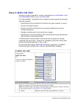
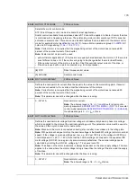
99.05
MOTOR CTRL MODE
FW block: None
Selects the motor control mode.
DTC (Direct torque control) mode is suitable for most applications.
Scalar control is suitable for special cases where DTC cannot be applied. In Scalar Control, the drive
is controlled with a frequency reference. The outstanding motor control accuracy of DTC cannot be
achieved in scalar control. There are some standard features that are disabled in the scalar control
mode, for example motor identification run (
), torque limits in parameter group
, DC
hold and DC magnetising (
).
Note:
Correct motor run requires that the magnetising current of the motor does not exceed 90
percent of the nominal current of the inverter.
Note:
Scalar control mode must be used
• with multimotor applications 1) if the load is not equally shared between the motors, 2) if the motors
are of different sizes, or 3) if the motors are going to be changed after the motor identification,
• if the nominal current of the motor is less than 1/6 of the nominal output current of the drive, or
• if the drive is used with no motor connected (e.g. for test purposes).
(0)
DTC
Direct torque control mode.
(1)
SCALAR
Scalar control mode.
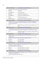
99.06
MOT NOM CURRENT
FW block: None
Defines the nominal motor current. Must be equal to the value on the motor rating plate. If several
motors are connected to the inverter, enter the total current of the motors.
Note:
Correct motor run requires that the magnetising current of the motor does not exceed 90
percent of the nominal current of the inverter.
Note:
This parameter cannot be changed while the drive is running.
0…32767 A
Nominal motor current.
Note:
The allowed range is 1/6…2 ×
I
2N
of drive for direct control
). For scalar
),
the allowed range is 0…2 ×
I
2N
of drive.
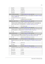
99.07
MOT NOM VOLTAGE
FW block: None
Defines the nominal motor voltage. Nominal voltage is a fundamental phase to phase rms voltage,
which is supplied to the motor at the nominal operating point. This parameter value must be equal to
the value on the asynchronous motor name plate.
Note:
Make sure the motor is connected correctly (star or delta) in accordance to the rating plate.
Note:
With permanent magnet motors, the nominal voltage is the BackEMF voltage (at motor nominal
speed). If the voltage is given as voltage per rpm, e.g. 60 V per 1000 rpm, the voltage for 3000 rpm
nominal speed is 3 × 60 V = 180 V. Note that the nominal voltage is not equal to the equivalent DC
motor voltage (E.D.C.M.) value given by some motor manufactures. The nominal voltage can be
calculated by dividing the E.D.C.M. voltage by 1.7 (= square root of 3).
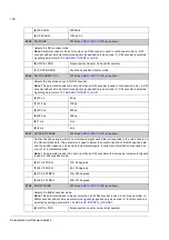
Note:
The stress on the motor insulations is always dependent on the drive supply voltage. This also
applies to the case where the motor voltage rating is lower than the rating of the drive and the supply
of the drive.
Note:
This parameter cannot be changed while the drive is running.
0…32767 V
Nominal motor voltage.
Note:
The allowed range is 1/6…2 ×
U
N
of drive.
Summary of Contents for ACSM1 Series
Page 1: ...ACSM1 Firmware Manual ACSM1 Speed and Torque Control Program...
Page 2: ......
Page 4: ......
Page 12: ...Table of contents 12...
Page 49: ...Drive control and features 49...
Page 282: ...Standard function blocks 282...
Page 306: ...Application program template 306...
Page 312: ...Control chain block diagrams 312...
Page 331: ...331...
Page 332: ...332...
Page 333: ......

