contact and insulated with basic insulation from other low-voltage circuits. The insulation
must be rated for the same voltage level as the drive main circuit. Note that extra-low
voltage circuits (such as 24 V DC) typically do not meet these requirements.
Alternative: You can connect the sensor with a basic insulation to the analog/digital
input(s) of the drive if you do not connect any other external control circuits to drive
digital and analog inputs.
3.
You can connect the sensor to the drive via an option module. The sensor and the
module must form a reinforced insulation between the motor live parts and the drive
control unit. See
Connecting motor temperature sensor to the drive via an option
4.
You can connect a sensor to a digital input of the drive via an external relay. The
insulation of the relay of must be rated for the main circuit voltage of the motor. See
Connection of motor temperature sensor to the drive via a relay (page 76)
.
■
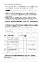
Connecting motor temperature sensor to the drive via an option module
This table shows:
•
the option module types that you can use for the motor temperature sensor connection
•
the insulation or isolation level that each option module forms between its temperature
sensor connector and other connectors
•
the temperature sensor types that you can connect to each option module
•
the temperature sensor insulation requirement in order to form, together with the
insulation of the option module, a reinforced insulation between the motor live parts and
the drive control unit.
Temperature sensor insulation
requirement
Temperature sensor
type
Option module
Pt100,
Pt1000
KTY
PTC
Insulation/Isolation
Type
Reinforced insulation
x
x
-
Galvanic isolation between sensor
connector and other connectors (in-
cluding drive control unit connector)
FIO-11
Reinforced insulation
-
x
x
Galvanic isolation between sensor
connector and other connectors (in-
cluding drive control unit connector)
FEN-xx
Basic insulation. Connectors of op-
tion module other than sensor con-
nector must be left unconnected.
x
x
x
Basic insulation between sensor
connector and drive control unit
connector. No insulation between
sensor connector and other I/O
connectors.
FAIO-01
No special requirement
-
-
x
Reinforced insulation between
sensor connector and other connect-
ors (including drive control unit con-
nector).
FPTC-
xx
1)
1) Suitable for use in safety functions (SIL2 / PL c rated).
■
Connection of motor temperature sensor to the drive via a relay
PTC alternative A: This table shows the insulation requirement for a customer’s external
relay, and the insulation requirement for the sensor to fulfill decisive voltage class A (double
insulation) of IEC 60800-5-1. The table also shows the insulation of the factory-installed
76 Guidelines for planning the electrical installation
Summary of Contents for ACS880-37LC
Page 1: ... ABB INDUSTRIAL DRIVES ACS880 37LC drives Hardware manual ...
Page 2: ......
Page 4: ......
Page 78: ...78 ...
Page 116: ...116 ...
Page 134: ...5 Set the real time clock 134 Maintenance ...
Page 144: ...144 ...
Page 167: ... Dimension drawing examples ACS880 37LC 0390A 7 with main contactor Dimensions 167 ...
Page 169: ...ACS880 37LC 1270A 7 with common motor terminal cubicle Dimensions 169 ...
Page 170: ...ACS880 37LC 1940A 7 with common motor terminal cubicle 170 Dimensions ...
Page 172: ...Location and size of input terminals Contact ABB for details 172 Dimensions ...
Page 174: ...Inverter module cubicle with two R8i modules bottom cable exit 174 Dimensions ...
Page 175: ...Inverter module cubicle with three R8i modules bottom cable exit Dimensions 175 ...
Page 176: ...Brake chopper cubicle D150 176 Dimensions ...
Page 178: ...Cubicle width 300 mm top cable exit 178 Dimensions ...
Page 179: ...Cubicle width 400 mm bottom cable exit Dimensions 179 ...
Page 180: ...Cubicle width 400 mm top cable exit 180 Dimensions ...
Page 181: ...Cubicle width 600 mm bottom cable exit Dimensions 181 ...
Page 182: ...Cubicle width 600 mm top cable exit 182 Dimensions ...
Page 198: ...198 ...
Page 200: ...200 ...


