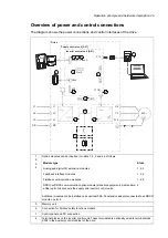
Fiber optic link to each inverter module. Similarly, each supply module is connected to the supply
control unit by fiber optic cables.
9
Terminal blocks for customer connections installed in the drive cabinet.
10
Supply unit (consisting of one or more supply modules)
11
DC intermediate link
12
Inverter unit (consisting of one or more inverter modules)
13
Optional brake chopper (+D150) and resistors (+D151)
14
Door switches and lights
■
Main disconnecting device (Q1.1)
Depending on the configuration of the drive, the main disconnecting device of the drive is
either a switch-disconnector or a main circuit breaker. Units with a switch-disconnector also
have a main contactor.
The main disconnecting device switches the main supply to the drive on and off. To
disconnect the main supply, turn the switch-disconnector to the 0 (OFF) position, or rack
out the main breaker (whichever device is installed).
WARNING!
The main disconnecting device does not isolate the input power terminals, AC
voltage meters, or the auxiliary voltage circuit from the power line. To isolate the
auxiliary voltage circuit, open the auxiliary voltage switch (Q21). To isolate the
input power terminals and AC voltage meters, open the main breaker of the supply
transformer.
To close the main disconnecting device, auxiliary voltage must be switched on, and the
grounding switch (if present) must be open.
■
Auxiliary voltage switch (Q21)
The auxiliary voltage switch controls the supply to the auxiliary voltage transformers. The
transformer feeds the control circuits inside the drive such as cooling fans, relays and
measuring equipment. The switch is fitted with fuses.
■
Grounding (earthing) switch (Q9.x), optional
The grounding switch (Q9.1, F259) connects the main AC power bus to the PE
busbar.
To close the grounding switch, auxiliary voltage must be switched on, and the main
disconnecting device must be open.
WARNING!
The grounding switch does not ground the input power terminals of the drive or
the auxiliary (control) voltage circuits.
■
Other devices on the door
•
Voltmeter (G334); comes with a phase selector switch.
Note:
The voltage is measured on the supply side of the main switch or breaker.
30 Operation principle and hardware description
Summary of Contents for ACS880-37LC
Page 1: ... ABB INDUSTRIAL DRIVES ACS880 37LC drives Hardware manual ...
Page 2: ......
Page 4: ......
Page 78: ...78 ...
Page 116: ...116 ...
Page 134: ...5 Set the real time clock 134 Maintenance ...
Page 144: ...144 ...
Page 167: ... Dimension drawing examples ACS880 37LC 0390A 7 with main contactor Dimensions 167 ...
Page 169: ...ACS880 37LC 1270A 7 with common motor terminal cubicle Dimensions 169 ...
Page 170: ...ACS880 37LC 1940A 7 with common motor terminal cubicle 170 Dimensions ...
Page 172: ...Location and size of input terminals Contact ABB for details 172 Dimensions ...
Page 174: ...Inverter module cubicle with two R8i modules bottom cable exit 174 Dimensions ...
Page 175: ...Inverter module cubicle with three R8i modules bottom cable exit Dimensions 175 ...
Page 176: ...Brake chopper cubicle D150 176 Dimensions ...
Page 178: ...Cubicle width 300 mm top cable exit 178 Dimensions ...
Page 179: ...Cubicle width 400 mm bottom cable exit Dimensions 179 ...
Page 180: ...Cubicle width 400 mm top cable exit 180 Dimensions ...
Page 181: ...Cubicle width 600 mm bottom cable exit Dimensions 181 ...
Page 182: ...Cubicle width 600 mm top cable exit 182 Dimensions ...
Page 198: ...198 ...
Page 200: ...200 ...


