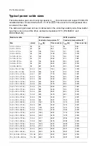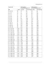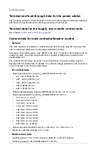
Terminal and lead-through data for the power cables
The locations and sizes of lead-throughs are shown by the dimension drawings delivered
with the drive, and the dimension drawing examples in this manual.
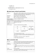
Terminal data for the supply and inverter control units
See chapter
Control units of the drive (page 99)
Contact data for main contactor/breaker control
■
General
The main contactor or breaker is controlled by the drive through relay K3. The relay has
one normally-open (NO) and one normally-closed (NC) contact.
Emergency stop options add a relay (K640) to the drive. To trip the main breaker upon an
emergency stop, one of the output switchover contacts of K640 must be wired to the
undervoltage coil.
The contacts of both relays are wired to a terminal block in the drive cubicle; see the
drive-specific circuit diagrams for details. The external voltage switched by the contacts is
to be connected to the same terminal block.
■
K3 contact data
•
Rated operational AC current (
I
e
) (IEC/EN 60947-5-1 AC 15):
•
24…127 V, 50/60 Hz: 6 A
•
220…240 V, 50/60 Hz: 4 A
•
400…440 V, 50/60 Hz: 3 A
•
500 V, 50/60 Hz: 2 A
•
690 V, 50/60 Hz: 2 A
•
Rated making/breaking capacity (IEC/EN 60947-5-1 AC 15): 10 ×
I
e
AC
•
Rated operational DC current (
I
e
) (IEC/EN 60947-5-1 DC 13):
•
24 V DC: 6 A / 144 W
•
48 V DC: 2.8 A / 134 W
•
72 V DC: 1 A / 72 W
•
110 V DC: 0.55 A / 60 W
•
125 V DC: 0.55 A / 69 W
•
220 V DC: 0.27 A / 60 W
•
250 V DC: 0.27 A / 68 W
•
400 V DC: 0.15 A / 60 W
•
500 V DC: 0.13 A / 65 W
•
600 V DC: 0.1 A / 60 W
•
Rated short-time withstand current (): 100 A for 1.0 s, 140 A for 0.1 s
•
Minimum switching capacity: 12 V / 3 mA
■
K640 contact data
•
Switching power: 3 VA or 3 W minimum, 2000 VA or 200 W maximum
•
Switching capacity, AC (IEC/EN 60947-5-1 AC 15):
154 Technical data
Summary of Contents for ACS880-37LC
Page 1: ... ABB INDUSTRIAL DRIVES ACS880 37LC drives Hardware manual ...
Page 2: ......
Page 4: ......
Page 78: ...78 ...
Page 116: ...116 ...
Page 134: ...5 Set the real time clock 134 Maintenance ...
Page 144: ...144 ...
Page 167: ... Dimension drawing examples ACS880 37LC 0390A 7 with main contactor Dimensions 167 ...
Page 169: ...ACS880 37LC 1270A 7 with common motor terminal cubicle Dimensions 169 ...
Page 170: ...ACS880 37LC 1940A 7 with common motor terminal cubicle 170 Dimensions ...
Page 172: ...Location and size of input terminals Contact ABB for details 172 Dimensions ...
Page 174: ...Inverter module cubicle with two R8i modules bottom cable exit 174 Dimensions ...
Page 175: ...Inverter module cubicle with three R8i modules bottom cable exit Dimensions 175 ...
Page 176: ...Brake chopper cubicle D150 176 Dimensions ...
Page 178: ...Cubicle width 300 mm top cable exit 178 Dimensions ...
Page 179: ...Cubicle width 400 mm bottom cable exit Dimensions 179 ...
Page 180: ...Cubicle width 400 mm top cable exit 180 Dimensions ...
Page 181: ...Cubicle width 600 mm bottom cable exit Dimensions 181 ...
Page 182: ...Cubicle width 600 mm top cable exit 182 Dimensions ...
Page 198: ...198 ...
Page 200: ...200 ...

