Electrical installation 43
Static electricity
WARNING!
Circuit boards contain components sensitive to electrostatic
discharge (ESD). Wear a grounding wrist band when handling the boards. Do not
touch the boards unnecessarily.
Optical components
Handle fiber optic cables with care. When unplugging optic cables, always grab the
connector, not the cable itself. Do not touch the ends of the fibers with bare hands as the
fiber is extremely sensitive to dirt.
Checking the insulation of the energy storage cable
WARNING!
Repeat the steps described in section
on page
. The complete safety instructions are given in
See
Safety instructions for ACS880 multidrive cabinets and modules
(3AUA0000102301 [English]). Ignoring the instructions can cause
physical injury or death, or damage to the equipment.
WARNING!
Open the DC switch/disconnector ([Q11], F286) of each
DC/DC converter.
Do not make any voltage tolerance or insulation resistance tests on the converter
modules. Every converter module has been tested for insulation between the main circuit
and the chassis at the factory.
Check the insulation resistance of the energy storage as instructed by its manufacturer.
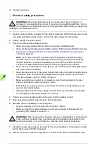
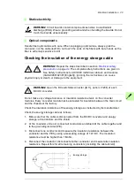
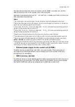
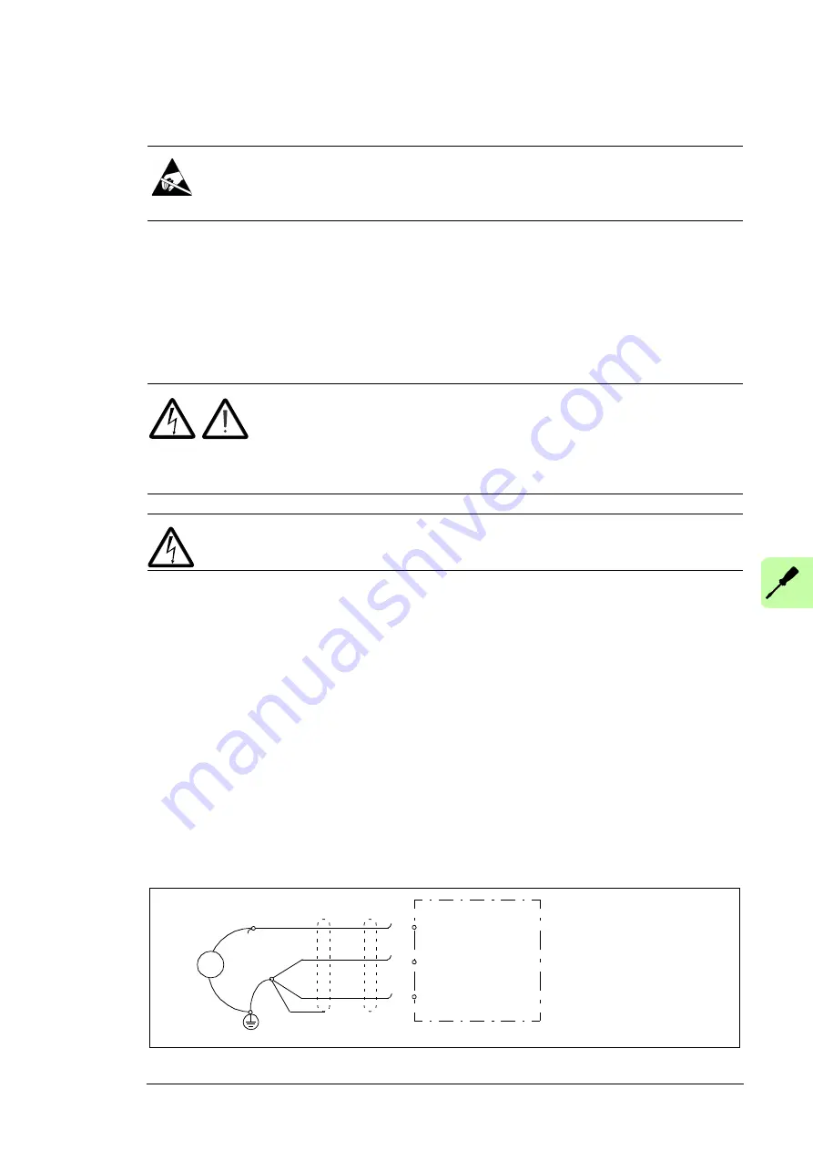
Check the energy storage cable as follows:
1. Make sure that the cable is disconnected from the DC/DC converter and energy
storage: all conductors and the shield.
2. At the converter unit end, connect all conductors and shield of the cable together and
to the grounding terminal (PE).
3. Disconnect one conductor and measure the insulation resistance between the
conductor and the PE by using a measuring voltage of 1 kV DC. The insulation
resistance must be higher than 1 Mohm
4. Reconnect the conductor, disconnect another conductor and measure its insulation
resistance. Repeat this for all remaining conductors (including the cable shield).
ohm
+
-
Energy storage
Summary of Contents for ACS880-1607
Page 1: ...ABB industrial drives Hardware manual ACS880 1607 DC DC converter units ...
Page 4: ......
Page 12: ...12 Introduction to the manual ...
Page 34: ...34 Mechanical installation ...
Page 40: ...40 Guidelines for planning electrical installation ...
Page 52: ...52 Electrical installation ...
Page 68: ...68 Start up ...
Page 80: ...80 Maintenance 7 3 4 5 6 ...
Page 82: ...82 Maintenance 3 4 5 6 7 8 9 9 ...
Page 85: ...Maintenance 85 12 Install and tighten the two screws 10 11 12 ...
Page 92: ...92 Maintenance 3 6 4 5 4 7a 7b 7b ...
Page 93: ...Maintenance 93 9 8 8 10 11 ...
Page 96: ...96 Maintenance 4 8 6 7 5 3 ...
Page 97: ...Maintenance 97 9 ...
Page 118: ...118 Dimensions Dimension drawings Frame 1 R8i bottom cable entry ...
Page 119: ...Dimensions 119 Frame 1 R8i top cable entry ...
Page 122: ...www abb com drives www abb com drivespartners 3AXD50000023644 Rev B EN 2017 01 30 Contact us ...

