2.
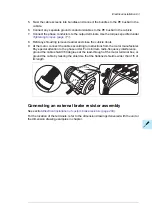
Open the door of the auxiliary control cubicle (ACU).
3.
Remove the shrouding at the top of the cubicle.
4.
Locate the inverter control unit (A41).
5.
Insert the module carefully into its position on the control unit.
6.
Fasten the mounting screw.
Note:
The screw tightens the connections and grounds the module. It is essential for fulfilling
the EMC requirements and for proper operation of the module.
■
Wiring of optional modules
See the appropriate optional module manual for specific installation and wiring instructions.
102 Electrical installation
Summary of Contents for ACS880-07CLC
Page 1: ...ABB industrial drives Hardware manual ACS880 07CLC drives ...
Page 2: ......
Page 4: ......
Page 64: ...64 ...
Page 82: ...82 ...
Page 91: ...PE PE 10 13 12 22 Electrical installation 91 ...
Page 122: ...122 ...
Page 124: ...124 ...
Page 132: ...5 4 11 7 6 8 132 Maintenance ...
Page 133: ...14 15 16 12 13 17 Maintenance 133 ...
Page 141: ...5 Set the real time clock Maintenance 141 ...
Page 142: ...142 ...
Page 150: ...150 ...
Page 176: ...ACS880 07CLC 0390A 7 C121 marine construction 176 Dimensions ...
Page 177: ...ACS880 07CLC 1310A 7 Dimensions 177 ...
Page 178: ...ACS880 07CLC 2180A 7 C121 marine construction 178 Dimensions ...
Page 179: ...ACS880 07CLC 3260A 7 C121 marine construction Dimensions 179 ...
Page 181: ... 2 D8D Dimensions 181 ...
Page 182: ... 3 D8D 182 Dimensions ...
Page 183: ... 4 D8D Dimensions 183 ...
Page 185: ...Inverter module cubicle with two R8i modules bottom cable exit Dimensions 185 ...
Page 186: ...Inverter module cubicle with three R8i modules bottom cable exit 186 Dimensions ...
Page 187: ...Brake chopper cubicle D150 Dimensions 187 ...
Page 188: ...188 ...
Page 202: ...202 ...
Page 211: ......
Page 212: ......
Page 214: ...Contact us www abb com drives 3AXD50000131457 Rev A EN EFFECTIVE 2018 03 09 3AXD50000131457A ...


