Additional information on the connections
■
External power supply for the control unit (XPOW)
The control unit is powered from a 24 V DC, 2 A supply through terminal block XPOW.
Using an external supply is recommended, if:
•
the control unit needs to be kept operational during input power breaks, for
example, because of continuous fieldbus communication
•
immediate restart is needed after a power break (that is, no control unit power-up
delay is allowed).
■
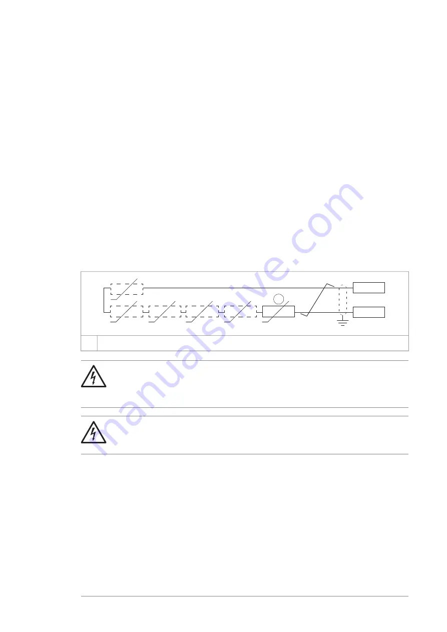
DI6 as a PTC sensor input
PTC sensors can be connected to this input for motor temperature measurement as
follows. The sensor can alternatively be connected to a FEN encoder interface module.
At the sensor end of the cable, leave the shields unconnected or ground them indirectly
via a high-frequency capacitor with a few nanofarads, for example 3.3 nF / 630 V. The
shield can also be grounded directly at both ends if they are in the same ground line
with no significant voltage drop between the end points. See the firmware manual of
the inverter unit for parameter settings.
1
...
+24V
DI6
+
t
°
+
t
°
+
t
°
+
t
°
+
t
°
+
t
°
1…6 PTC thermistors connected in series
1
WARNING!
As the inputs pictured above are not insulated according to IEC 60664, the
connection of the motor temperature sensor requires double or reinforced
insulation between motor live parts and the sensor.
WARNING!
Make sure that the voltage does not exceed the maximum permitted voltage
of the PTC sensor.
■
AI1 or AI2 as a Pt100, Pt1000, PTC or KTY84 sensor input
Sensors for motor temperature measurement can be connected between an analog
input and output, an example connection is shown below. (Alternatively, you can
connect the KTY to an FIO-11 or FAIO-01 analog I/O extension module or a FEN encoder
interface module.) At the sensor end of the cable, leave the shields unconnected or
ground them indirectly via a high-frequency capacitor with a few nanofarads, for
example 3.3 nF / 630 V. The shield can also be grounded directly at both ends if they
are in the same ground line with no significant voltage drop between the end points.
Control unit of the drive 105
Summary of Contents for ACS880-04F-504A-3
Page 1: ... ABB INDUSTRIAL DRIVES ACS880 04F drive modules Hardware manual ...
Page 2: ......
Page 4: ......
Page 26: ...26 ...
Page 36: ...36 ...
Page 44: ...44 ...
Page 50: ...50 Mechanical installation ...
Page 56: ...56 ...
Page 116: ...116 ...
Page 122: ...4 3 2 122 Maintenance ...
Page 128: ...128 ...
Page 143: ... Package dimensions Package dimensions without IP shroud kit Technical data 143 ...
Page 158: ...158 ...
Page 160: ...Standard configuration IP20 UL Type Open 160 Dimension drawings ...
Page 161: ...Drive module with options E208 and H370 IP20 UL Type Open Dimension drawings 161 ...
Page 162: ...Drive module with options 0B051 E208 0H371 IP00 UL Type Open 162 Dimension drawings ...
Page 163: ...Drive module with options 0B051 E208 0H371 C217 IP00 UL Type Open Dimension drawings 163 ...
Page 164: ...Drive module with options 0B051 0H371 IP00 UL Type Open 164 Dimension drawings ...
Page 165: ...Mounting plate opening 3AXD50000038119 Dimension drawings 165 ...
Page 166: ...3AXD50000038119 166 Dimension drawings ...
Page 167: ...External control unit 3AXD50000011687 Dimension drawings 167 ...
Page 168: ...168 ...


