

Warning!
For floating networks remove
screws at F1 and F2 on Frame sizes R5 or
R6.
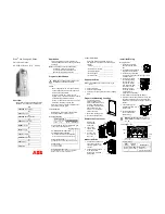
9. Install the cable clamp(s)
for the control cable(s).
(Power/motor cables and
clamps not shown in
figure.)
Wiring the Controls
1. Strip control cable sheathing
and twist the copper screen
into a pig-tail.
2. Route control cable(s)
through clamp(s) and
tighten clamp(s).
3. Connect the ground screen
pig-tail for digital and analog
I/O cables at X1-1.
4. Connect the ground screen
pig-tail for RS485 cables at
X1-28 or X1-32.
5. Strip and connect the individual control wires to
the drive terminals. For details, or other
configurations, see “Control Connections” in
the User’s Manual.
6. Install the conduit/gland box cover (1 screw).
Check Installation
Before applying power, perform the following
checks.
Re-install the Cover
1. Align the cover
and slide it on.
2. Tighten the
captive screw.
3. Re-install the
control panel.
Apply Power
Always re-install the front cover before turning
power on.
Warning!
The ACS550 will start up
automatically at power up, if the external
run command is on.
1. Apply input power.
When power is applied to the ACS550, the
green LED comes on.
Note!
Before increasing motor speed, check that
the motor is running in the desired direction.
Start-up
In Start-up, enter motor data (collected earlier)
and, if needed, edit parameters that define how
the drive operates and communicates.
Assistant Control Panel
The Start-up Assistant steps through typical
start-up selections, and runs automatically
upon the initial power up. At other times, use
the steps below to run the Start-up Assistant.
1. Use the MENU key to
access the Menu list.
2. Select Assistants.
3. Select Start-up Assistant.
4. Follow the screen
instructions to configure
the system.
Note!
For common parameters and menu items,
use the Help key
to display
descriptions.
If you encounter Alarms or Faults, use the
Help key or refer to the Diagnostic section
of the User’s Manual.
Basic Control Panel
The Basic Control Panel does not
include the Start-up Assistant. Refer
to the Start-up Section of the User’s
Manual and manually enter any
parameter changes desired.
X0035
Power Output to Motor
PE
(U2, V2, W2)
Optional Braking
Frame
Size
Terminal
Labels
Brake Options
R5, R6 UDC+, UDC- • Braking unit
• Chopper and resistor
GND
Power Input
F1
(U1, V1, W1)
F2
Power Output to Motor
PE
(U2, V2, W2)
GND
Power Input
(U1, V1, W1)
X0013
F2
F1
Frame Size R5
Frame Size R6
9
X0006
3
IP2003
1
5
1
SCR
2
AI1
3
AGND
4
10V
5
AI2
6
AGND
7
AO1
8
AO2
9
AGND
10 24V
11 GND
12 DCOM
13 DI1
14 DI2
15 DI3
16 DI4
17 DI5
18 DI6
19 RO1C
20 RO1A
21 RO1B
22 RO2C
23 RO2A
24 RO2B
25 RO3C
26 RO3A
27 RO3B
Ext. freq. ref. 1: 0…10 V
Ref. voltage 10 VDC
Output freq.: 0…20 mA
Start/Stop: Active = start
Fwd/Rev: Active = rev. dir.
Constant speed sel.
2
Constant speed sel.
2
Ramp pair: Active = 2
nd
ramp pair.
Relay output 1
Default operation:
Relay output 2
Default operation:
Relay output 3
Default operation:
X1
Output current: 0…20 mA
Not used
Analog input com.
Not used
Analog output com
Aux. volt. 24 VDC
Aux. volt. common
Digital input com. for all
Signal cable shield
Analog input com.
Ready = 19/21 connected
Running = 22/24 connected
Fault(-1) =25/27 connected
(Fault => 25/26 connected)
Note 1.
Jumper setting:
Note 2.
Code: 0 = open, 1 = connected
DI3
DI4
Output
0
0
Reference through AI1
1
0
CONSTANT
SPEED
1 (1202)
0
1
CONSTANT
SPEED
2 (1203)
1
1
CONSTANT
SPEED
3 (1204)
J1
AI1: 0…10 V
AI2: 0(4)…20 mA
ON
ON
Check
Environment conforms to specifications.
The drive is mounted securely.
Proper cooling space around the drive.
Motor and driven equipment are ready for start.
Floating networks: Internal RFI filter
disconnected.
Drive is properly grounded.
Input power (mains) voltage matches the drive
nominal input voltage.
The input power (mains) terminals, U1, V1, W1,
are connected and tightened as specified.
The input power (mains) fuses / mains switch
installed.
The motor terminals, U2, V2, W2, are
connected and tightened as specified.
Motor cable is routed away from other cables.
NO power factor compensation capacitors are
connected to the motor cable.
Control terminals are wired and tightened as
specified.
NO tools or foreign objects (such as drill
shavings) are inside the drive.
NO alternate power source for the motor is
connected – no input voltage is applied to the
output of the drive.
3
1
2
IP2009
LOC
DIR
12:45
MENU
400RPM
1200 RPM
12.4 A
405 dm3/s
?
C
od
e
: 3
A
FE
6
824
3
513
REV A /
EN
Ef
fe
cti
ve:
S
e
ptem
ber 9
, 20
03
Sup
ersed
es:
NO
N
E


