background image

10   Configuration

ACS355 drive configuration

The AC500 Modbus application macro makes the necessary changes to parameter default 
values for use in the starter kit. To activate the macro, set parameter 9902 APPLIC 
MACRO to AC500 MODBUS (10) as shown below. The macro is available in ACS355 
drives with software version 503C or above.

The AC500 Modbus application macro default drive parameters correspond to the ABB 
standard macro for ACS355, with the following changes:
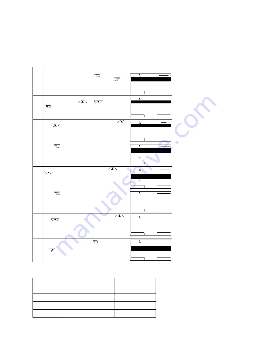
Step Action

Display

1.

Go to the Main menu by pressing 

 if you are in the 

Output mode, otherwise by pressing repeatedly 

 until 

you get to the Main menu.

2.

Go to the Parameters mode by selecting PARAMETERS 
on the menu with keys 

 and 

, and pressing 

.

3.

Select the appropriate parameter group with keys 


and .

Press . 

4.

Select the appropriate parameter with keys 

 and 

. The current value of the parameter is shown 

below the selected parameter.

Press .

5.

Specify a new value for the parameter with keys 


and .
Pressing the key once increments or decrements the 
value. Holding the key down changes the value faster. 
Pressing the keys simultaneously replaces the displayed 
value with the default value.

6.

• To save the new value, press 

.

• To cancel the new value and keep the original, press 

.

Parameter

Name

Value

1001

EXT1 COMMANDS

COMM (10)

1102

EXT1/EXT2 SEL

COMM (8)

1103

REF1 SEL

COMM (8)

1604

FAULT RESET SEL

COMM (8)

MENU

EXIT


PARAMETERS

ASSISTANTS

CHANGED PAR

EXIT

ENTER

00:00

LOC

MAIN MENU

1

ENTER


01 OPERATING DATA

03 FB ACTUAL SIGNALS

04 FAULT HISTORY

10 START/STOP/DIR

11 REFERENCE SELECT

EXIT

SEL

00:00

LOC

PAR GROUPS

01


99 START-UP DATA

01 OPERATING DATA

03 FB ACTUAL SIGNALS

04 FAULT HISTORY

10 START/STOP/DIR

EXIT

SEL

00:00

LOC

PAR GROUPS

99

SEL


9901 LANGUAGE

ENGLISH

9902 APPLIC MACRO

9903 MOTOR TYPE

9904 MOTOR CTRL MODE

EXIT

EDIT

00:00

LOC

PARAMETERS


9901 LANGUAGE

9902 APPLIC MACRO

ABB STANDARD

9903 MOTOR TYPE

9904 MOTOR CTRL MODE

EXIT

EDIT

00:00

LOC

PARAMETERS

EDIT


9902 APPLIC MACRO


CANCEL

SAVE

00:00

PAR EDIT

[1]

ABB STANDARD

LOC


9902 APPLIC MACRO


PAR EDIT

CANCEL

SAVE

00:00

LOC

[10]

AC500 MODBUS

SAVE

CANCEL


9901 LANGUAGE

9902 APPLIC MACRO

3-WIRE

9903 MOTOR TYPE

9904 MOTOR CTRL MODE

EXIT

EDIT

00:00

LOC

PARAMETERS

AC500 MODBUS

Summary of Contents for ACS355 series

Page 1: ...Application guide ACS355 and AC500 eCo...

Page 2: ...g the online help in CoDeSys on page 15 Drive and PLC hardware manuals and guides Code English ACS355 user s manual 3AUA0000066143 2 AC500 eCo and ACS355 quick installation guide 2CDC125145M0201 1 Sys...

Page 3: ...Application guide ACS355 and AC500 eCo 2CDC125152M0201 Rev A EN EFFECTIVE 2011 01 21 2011 ABB All Rights Reserved Table of contents...

Page 4: ......

Page 5: ...ntains 15 Getting help 15 Using the online help in CoDeSys 15 Getting started AC500 15 AC500 ACS Drives Libraries topics 15 Getting help on a specific function block 16 Configuring the Modbus settings...

Page 6: ...am 24 DriveRef 25 Main components of the example program 25 Modbus RTU communication function block FB_COM 25 Basic control block FB_BASIC CONTROL 25 Speed reference generation 26 Other control blocks...

Page 7: ...sed with the ACS355 and AC500 eCo starter kit Safety instructions Follow all safety instructions delivered with the starter kit Read the complete safety instructions for the ACS355 drive before you in...

Page 8: ...ition to this manual the delivery includes the following manuals Quick installation guide which describes the mechanical and electrical installation of the starter kit ACS355 user s manual which descr...

Page 9: ...d how to configure the ACS355 drive and AC500 eCo PLC for use The instructions in this chapter are intended to be used after the mechanical and electrical installation has been completed as explained...

Page 10: ...ecrements the value Holding the key down changes the value faster Pressing the keys simultaneously replaces the displayed value with the default value 6 To save the new value press To cancel the new v...

Page 11: ...Click Tools 5 Click TK503 TK504 cable driver The TK503_TK504 programming cable Driver Installer window opens 6 Click Install The installation begins Installing PS553 DRIVES libraries Note ABB PS501 C...

Page 12: ...2 Click File Open 3 Browse to the folder C Program Files ABB ABB Configurator Projects Examples Drives_PS553 DRIVES ACS355_PM554_ModbusRTU and open ACS355_PM554_ModbusRTU pro A dialog opens asking if...

Page 13: ...n parameter to COMx for TK504 1 In CoDeSys click Online Communication Parameters The Communication Parameters window opens 2 Click New The Communication Parameters New Channel window opens 3 In the Na...

Page 14: ...14 Configuration The status of the function blocks is displayed...

Page 15: ...line help click Help Contents See the sections below for more detailed information on AC500 help topics Getting started AC500 In the Contents tab expand Target System AC500 S500 Introduction Getting S...

Page 16: ...left pane select the Resources tab 2 Click PLC Configuration 3 In the middle pane under AC500 expand Interfaces FIX 4 Click COM1 MODBUS SLOT 5 In the right pane Module parameters configure the follow...

Page 17: ...r s manual 3AUA0000066143 English To configure the slave address in CoDeSys follow the instructions below 1 In CoDeSys in the left pane select the POUs tab 2 Click PRG_Drive1 PRG 3 In the modbus RTU c...

Page 18: ...t of the new drive 5 In the POUs tab double click PLC_PRG PRG 6 Right click the gray bar with 0001 on it see the picture and click Copy 7 Right click again and click Paste The copied instance of the p...

Page 19: ...click the PLC_VISU element to open the visualization 2 Copy paste the elements of the first drive ie right click and Copy then right click and Paste each of them 3 Arrange the copied elements for exam...

Page 20: ...n to control the drive disconnect all inputs of the function block to be controlled with the visualization in the program For example to control START STOP_COAST RESET and SPEED_REF through the visual...

Page 21: ...n the ACS3XX_COM_MOD_RTU function block change the value of NVAR_READ to correspond to the number of parameters read 1 the number includes the status word 3 Go back online by clicking Online Login An...

Page 22: ...parameters mapped to be read For example if parameter 53 13 is set to 110 01 10 DRIVE TEMP awACT_PARAMETERS 5 gets the value of the parameter Word to integer conversion for variables with negative va...

Page 23: ...overview The main advantage of using function blocks is that it is easy to control drives and there is no need to master the details of the ABB Drives profile Function block programming also allows f...

Page 24: ...ram includes a call to PRG_Drive1 see below If there are multiple drives add a program for each additional drive see Adding another drive on page 17 PRG_Drive1 program PRG_Drive1 contains the function...

Page 25: ...s used the LineCom1 variable in the LINE_TOKEN input must be declared as global See Information on LineCom1 as a global variable on page 18 For a description of the DRIVE_DATA variable DriveRef see Dr...

Page 26: ...parameter REF1 MAX is 500 which corresponds to 50 Hz Vector mode In the vector mode the drive paramter REF1 MAX is set to the maximum speed given in rpm eg 1500 If you change the motor control mode th...

Page 27: ...on blocks and program structure 27 ACS_DRIVES_CTRL_ENG For system applications the engineering block ACS_DRIVES_CTRL_ENG can be used Refer to the online help for a detailed description of the function...

Page 28: ...28 Function blocks and program structure...

Page 29: ......

Page 30: ...cal changes or modify the contents of this document without prior notice With regard to purchase orders the agreed particulars shall prevail ABB AG does not accept any responsibility whatsoever for po...

Reviews: