background image

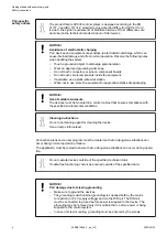
CAUTION!
Do not obstruct the ventilation for cooling!

The ventilation slots on the upper and lower sides of the devices must not be

covered.

CAUTION!
Run signal and power wiring separately!

Signal and supply lines (power cables) must be laid out so that no malfunctions

due to capacitive and inductive interference can occur (EMC).

WARNING!
Warning sign on the module!

This indicates that dangerous voltages may be present or that surfaces may

have dangerous temperatures.

WARNING!
Splaying of strands can cause hazards!

Avoid splayed strands when wiring terminals with stranded conductors.

Ferrules can be used to prevent splaying.

WARNING!
Removal/Insertion under power

Removal or insertion under power is permissible only if all conditions for hot

swapping are fullfilled.

The devices are not designed for removal or insertion under power when the

conditions for hot swap do not apply. Because of unforeseeable consequences,

it is not allowed to plug in or unplug devices with the power being ON.

Make sure that all voltage sources (supply and process voltage) are switched

off before you

connect or disconnect any signal or terminal block

remove, mount or replace a module.

Disconnecting any powered devices while they are energized in a hazardous

location could result in an electric arc, which could create an ignition source

resulting in fire or explosion.

Prior to proceeding, make sure that power is been disconnected and that the

area has been thoroughly checked to ensure that flammable materials are not

present.

The devices must not be opened when in operation. The same applies to the

network interfaces.


Getting started with example projects

Safety instructions 

2023/03/03

3ADR010649, 3, en_US

5

Summary of Contents for AC500 V2

Page 1: ...INSTALLATION AND CONFIGURATION MANUAL Getting started AC500 V2 products ...

Page 2: ...ns 13 1 5 2 Create set up and save your AC500 V2 project 13 1 5 3 Configure the I O module 17 1 5 4 Programming and compiling 19 1 5 5 Setting up the communication gateway 30 1 5 6 Log in to CPU and download the program 35 1 5 7 Test the program 37 1 5 8 Set up visualization 39 1 5 9 Reset the CPU 51 1 6 Example project for remote I O expansion with PROFINET 52 1 6 1 Preconditions 52 1 6 2 Set up ...

Page 3: ...pairs is rejected Both the AC500 control system and other components in the vicinity are operated with dan gerous touch voltages Touching live components can lead to serious health implications or even death To avoid such risks and the occurrence of property damage persons involved in the installation commissioning and maintenance must have relevant knowledge about Automation technology Handling o...

Page 4: ... that ensures compliance with the specified environmental conditions Cleaning instructions Do not use cleaning agent for cleaning the device Use a damp cloth instead Connection plans and a user program must be created so that no dangerous situations can occur during normal operation or failure The application must be tested to ensure that no dangerous situations can occur during opera tion Do not ...

Page 5: ...ping are fullfilled The devices are not designed for removal or insertion under power when the conditions for hot swap do not apply Because of unforeseeable consequences it is not allowed to plug in or unplug devices with the power being ON Make sure that all voltage sources supply and process voltage are switched off before you connect or disconnect any signal or terminal block remove mount or re...

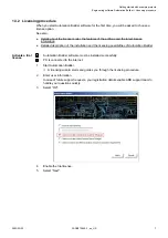
Page 6: ...download Ä Further information on page 6 1 3 1 Installing Automation Builder You must have admininstrator rights on your PC to install Automation Builder In case of an update installation Create a project archive before upgrading Automation Builder Project archives contain all project data including data that is not stored with a project file e g device description files for third party devices 1 ...

Page 7: ...mation Builder software must be installed successfully PC is connected to the internet 1 Start Automation Builder ð A licensing wizard starts and guides you through the licensing procedure 2 Enter user information In case of future support requests your registration details enable ABB support team to handle your questions quickly 3 Select OK 4 Enable the trial license 5 Select Next Activate a tria...

Page 8: ... activation and select Next ð License activation procedure starts A successfully ended licensing procedure ends with a success message Getting started with example projects Engineering software Automation Builder Licensing procedure 2023 03 03 3ADR010649 3 en_US 8 ...

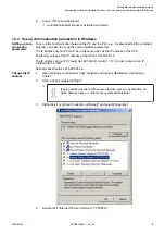
Page 9: ...Avoid X 10 in order to prevent an IP conflict with the CPU Subnet mask should be 255 255 255 0 1 Open Windows control panel Click Network and Internet è Network and Sharing Center 2 Click Change adapter settings ð If using existing network with several devices please pay attention on given network rules or contact your system administrator 3 Right click Local Area Connection Ethernet and select Pr...

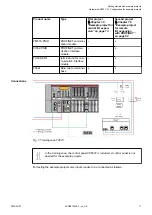
Page 10: ...AC500 V2 PLC Product name Type First project Ä Chapter 1 5 Example project for central I O expan sion on page 13 Second project Ä Chapter 1 6 Example project for remote I O expansion with PROFINET on page 52 PM585 ETH AC500 V2 CPU x x TB521 ETH terminal base for CPU x x DA501 analog digital mixed input output I O module x x TU516 H terminal unit for I O module x x Getting started with example proj...

Page 11: ...n interface module x TU508 ETH terminal unit for com munication interface module x TA524 blind cap for terminal base x x Fig 1 Training case TA515 In the training case the control panel CP6607 is included A control panel is not needed for the example projects For testing the example project some inputs require to be connected as follows Connections Getting started with example projects Hardware AC...

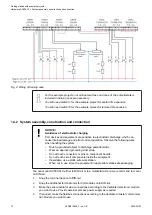
Page 12: ...ing wrist strap Do not touch connectors or pins on component boards Do not touch circuit components inside the equipment If available use a static safe workstation When not in use store the equipment in appropriate static safe packaging You can mount AC500 PLC either to DIN rail or to a metal plate Here we recommend to mount on DIN rail 1 Snap the terminal base onto DIN rail 2 Snap the additional ...

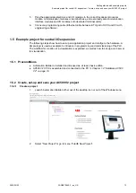
Page 13: ...in programming and commissioning of the PLC The workflow for creation of a visualization is explained as well as how to set up a web server for visualization 1 5 1 Preconditions Automation Builder is installed and licensed as at least basic edition AC500 V2 CPU is assembled and connected to the PC Ä Chapter 1 4 Hardware AC500 V2 on page 10 1 5 2 Create set up and save your AC500 V2 project 1 5 2 1...

Page 14: ... location to save the project to 7 Select OK 8 Select PLC AC500 V2 9 Select the CPU according to your hardware set up Getting started with example projects Example project for central I O expansion Create set up and save your AC500 V2 project 2023 03 03 3ADR010649 3 en_US 14 ...

Page 15: ...elect Add PLC to add the CPU to your application Getting started with example projects Example project for central I O expansion Create set up and save your AC500 V2 project 2023 03 03 3ADR010649 3 en_US 15 ...

Page 16: ...Under parameter Check battery choose the value Off since there is no battery present inside the CPU module 4 Keep the default values for all other parameters Getting started with example projects Example project for central I O expansion Create set up and save your AC500 V2 project 2023 03 03 3ADR010649 3 en_US 16 ...

Page 17: ...modules in the Automation Builder project must match the real hardware configuration The position of the modules in the device tree can be changed by drag and drop 1 5 3 1 Add an I O bus module 1 Right click IO_Bus in the device tree 2 Select Add object Getting started with example projects Example project for central I O expansion Configure the I O module 2023 03 03 3ADR010649 3 en_US 17 ...

Page 18: ...ing 1 Double click DA501 in the device tree ð A tab opens in the editor view 2 Select DA501 I O Mapping ð Here you will map variable names symbols for the channels you will need in the program Getting started with example projects Example project for central I O expansion Configure the I O module 2023 03 03 3ADR010649 3 en_US 18 ...

Page 19: ...he digital output variables 1 Open the list of the digital outputs 2 Fill in the variable names Channel Type Variable Digital output DC16 BOOL xStartDrilling1 1 5 4 Programming and compiling You write the program code in a separate IEC 61131 3 editor CODESYS You can open CODESYS out of Automation Builder Supported programming languages ST Structured Text IL Instruction List FBD Function Block Diag...

Page 20: ... of a user program IEC application which defines by parameters the way and the speed the CPU is executing the user program For this project you will use only one cycling task Open CODESYS editor Ä Chapter 1 5 4 1 Starting the IEC 61131 programm editor CODESYS on page 20 1 In the CODESYS editor menu select the Resources tab 2 Double click Task configuration ð The Task configuration window opens Get...

Page 21: ...Select Append Task 5 Enter a name 6 Set Priority to 15 7 Set Type to cyclic 8 Set Interval to T 10ms Getting started with example projects Example project for central I O expansion Programming and compiling 2023 03 03 3ADR010649 3 en_US 21 ...

Page 22: ...et in milliseconds with IEC time syntax Watchdog calls To keep track of the time it takes to complete the task Calls You can call in one or more program POUs in one single task 11 Right click the watch icon next to Term_01_Task 12 Select Append Program Call 13 Select ð The input assistant opens 14 Select PLC_PRG PRG 15 Select OK ð The task has been appended Getting started with example projects Ex...

Page 23: ... Structured Text editor Keep this setting because of good visibility of the instructions at a glance and good handling for trouble shooting 1 5 4 4 Boolean logic NOT 1 5 4 4 1 Application example driller Recognizing of a driller by a photo sensor TRUE input signal from sensor indicates that a driller is broken If driller has been found correct then start drilling Getting started with example proje...

Page 24: ...1 DC16 xStartDrilling1 Motor on 1 5 4 4 2 Implementation Create a new program POU in the project 1 In the CODESYS menu select POUs 2 Select Add object 3 Enter _01_Assignment_NOT 4 Set Type of POU to Program 5 Set Language of the POU to Function Block Diagram FBD 6 Select OK ð POU has been added Getting started with example projects Example project for central I O expansion Programming and compilin...

Page 25: ...inside of the first Network 3 Select Assign from Tools 4 Select on the left side of the assignment and press F2 ð Input Assistant opens 5 Under Global Variables open DA501_Module_Mapping Getting started with example projects Example project for central I O expansion Programming and compiling 2023 03 03 3ADR010649 3 en_US 25 ...

Page 26: ...ll replace the 9 Press Enter ð Declare Variable opens You see the written variable name and the data type BOOL The scope is VAR It means it is a local variable within this POU 10 Select OK to accept the entries Getting started with example projects Example project for central I O expansion Programming and compiling 2023 03 03 3ADR010649 3 en_US 26 ...

Page 27: ...to the left side of the instruction line 3 Select on the right side of the instruction line then press F2 ð Input Assistant opens 4 Under Global Variables open DA501_Module_Mapping 5 Select xStartDrilling1 6 Select OK to close the dialog 7 Right click the left side of assignment PIN Getting started with example projects Example project for central I O expansion Programming and compiling 2023 03 03...

Page 28: ... the POU in the PLC_PRG 1 Double click PLC_PRG 2 Select the first line in PLC_PRG and press F2 ð Input Assistant opens Getting started with example projects Example project for central I O expansion Programming and compiling 2023 03 03 3ADR010649 3 en_US 28 ...

Page 29: ...In the CODESYS editor menu select Project è Build ð The result of the compiling is shown in the Messages field at the bottom of the screen If you skip the compiling and select Login the Automation Builder will automatically trigger compiling in advance to logging in Getting started with example projects Example project for central I O expansion Programming and compiling 2023 03 03 3ADR010649 3 en_...

Page 30: ...92 168 0 10 The IP address of your PC should be 192 168 0 X Avoid X 10 in order to prevent an IP conflict with the CPU Subnet mask should be 255 255 255 0 1 Open Windows control panel Click Network and Internet è Network and Sharing Center 2 Click Change adapter settings ð If using existing network with several devices please pay attention on given network rules or contact your system administrato...

Page 31: ...4 Double click Internet Protocol Version 4 TCP IPv4 Getting started with example projects Example project for central I O expansion Setting up the communication gateway 2023 03 03 3ADR010649 3 en_US 31 ...

Page 32: ...5 Enter your desired IP address and subnet mask Getting started with example projects Example project for central I O expansion Setting up the communication gateway 2023 03 03 3ADR010649 3 en_US 32 ...

Page 33: ... address of the CPU or type in the current IP address if differs The standard default IP address of the port ETH1 is 192 168 0 10 The standard default IP address of the port ETH2 is 192 168 1 10 Setting up the communication gateway Getting started with example projects Example project for central I O expansion Setting up the communication gateway 2023 03 03 3ADR010649 3 en_US 33 ...

Page 34: ...ion about the current selected CPU After changing the IP Address either double click the Application or right click and Create Configuration Data Check commu nication set tings Getting started with example projects Example project for central I O expansion Setting up the communication gateway 2023 03 03 3ADR010649 3 en_US 34 ...

Page 35: ...to the CPU will load the project into the AC500 V2 CPU The first log in will also load the hardware set up Getting started with example projects Example project for central I O expansion Log in to CPU and download the program 2023 03 03 3ADR010649 3 en_US 35 ...

Page 36: ...t Yes to download the application to the AC500V2 CPU ð PLC is in stop mode 3 Start the PLC Ä Chapter 1 5 7 1 Start the program execution on page 37 Getting started with example projects Example project for central I O expansion Log in to CPU and download the program 2023 03 03 3ADR010649 3 en_US 36 ...

Page 37: ...ject is stored in the RAM memory The project is stored in the flash EEPROM if boot application was created 1 5 7 Test the program 1 5 7 1 Start the program execution You are logged in the CPU An executable project is loaded to the CPU The CPU is in stop mode Open CODESYS Ä Chapter 1 5 8 1 Starting the IEC 61131 programm editor CODESYS on page 40 In the CODESYS editor menu select Online è Run Alter...

Page 38: ...e online status of inputs and outputs within the POU 1 5 7 3 Stop the program execution You are logged in the CPU An executable project is loaded to the CPU Getting started with example projects Example project for central I O expansion Test the program 2023 03 03 3ADR010649 3 en_US 38 ...

Page 39: ...sualization allows designing a graphical representation of project variables In online mode the graphical elements can change for example their color size or position according to the actual variable status Visualization for your project is done via CODESYS editor Getting started with example projects Example project for central I O expansion Set up visualization 2023 03 03 3ADR010649 3 en_US 39 ...

Page 40: ...on Builder device tree double click Application ð This will start the IEC 61131 programm editor CODESYS 1 5 8 2 Insert visualization object 1 In the CODESYS menu select Visualization 2 Right click Visualizations 3 Select Add object Getting started with example projects Example project for central I O expansion Set up visualization 2023 03 03 3ADR010649 3 en_US 40 ...

Page 41: ...ill be useful to choose another name e g _01_Assignment_NOT_v and to choose PLC_VISU as a home screen to access all available visualization screens The name of a visualization object can be modified afterwards 1 5 8 3 Creating and configuring of visualization 1 In the CODESYS device tree right click PLC_VISU 2 Select Object Properties Getting started with example projects Example project for centr...

Page 42: ...3 Enable Web Visualization Getting started with example projects Example project for central I O expansion Set up visualization 2023 03 03 3ADR010649 3 en_US 42 ...

Page 43: ...ualization you can create a rectangle 3 Double click the shape Alternatively right click and then select Configure ð The Regular Element Configuration window opens 4 Under Category select Text Getting started with example projects Example project for central I O expansion Set up visualization 2023 03 03 3ADR010649 3 en_US 43 ...

Page 44: ...n 8 Select OK to implement changes 1 5 8 5 Further lines and labels 1 In the CODESYS editor toolbox select Polyline 2 Create a line by left clicking and holding the mouse button Drag the line to your desired lenght then double click to end the line Getting started with example projects Example project for central I O expansion Set up visualization 2023 03 03 3ADR010649 3 en_US 44 ...

Page 45: ...ble Grid and check Settings 1 In the CODESYS editor right click anywhere on the visualization and select Settings 2 Select Grid and unmark Visible Getting started with example projects Example project for central I O expansion Set up visualization 2023 03 03 3ADR010649 3 en_US 45 ...

Page 46: ...3 Select Frame and make sure WebVisu is activated Getting started with example projects Example project for central I O expansion Set up visualization 2023 03 03 3ADR010649 3 en_US 46 ...

Page 47: ...se and adapt size if required 2 Double click on the ellipse to open the configuration 3 Select Colors and set two different colors for Color and Alarm color Getting started with example projects Example project for central I O expansion Set up visualization 2023 03 03 3ADR010649 3 en_US 47 ...

Page 48: ...4 Open Variables and left click Change color Getting started with example projects Example project for central I O expansion Set up visualization 2023 03 03 3ADR010649 3 en_US 48 ...

Page 49: ...l open the Input assistant 6 In DA501_Module_Mapping select xStartDrilling1 7 Select OK Getting started with example projects Example project for central I O expansion Set up visualization 2023 03 03 3ADR010649 3 en_US 49 ...

Page 50: ...ottom of the screen If you skip the compiling and select Login the Automation Builder will automatically trigger compiling in advance to logging in 1 5 8 9 Save CODESYS project In the CODESYS editor menu select File è Save Alternatively select the save icon in the tool bar Alternatively press Ctrl S Getting started with example projects Example project for central I O expansion Set up visualizatio...

Page 51: ...rties PERSISI TENT and RETAIN this command resets all variables except R variables Reset origin All variables and the application project are reset Table 4 Behavior of variables of type VAR local or global and variables of type PERSISTENT RETAIN VAR VAR PERSISTENT RETAIN After online command Online change no change no change After online command Download initialization no change After online comma...

Page 52: ...entral I O expansion Ä Chapter 1 5 Example project for central I O expansion on page 13 CM579 PNIO communication module is inserted in terminal base and connected to the PLC Ä Chapter 1 4 Hardware AC500 V2 on page 10 CI502 PNIO communication interface module is inserted in terminal unit and connected to the PLC Ä Chapter 1 4 Hardware AC500 V2 on page 10 1 6 2 Set up PROFINET controller 1 6 2 1 Add...

Page 53: ...general behavior 1 Under Extension_Bus double click CM579_PNIO in the device tree ð A tab opens in the editor view Getting started with example projects Example project for remote I O expansion with PROFINET Set up PROFINET controller 2023 03 03 3ADR010649 3 en_US 53 ...

Page 54: ...up the PROFINET IO controller To edit settings for the controller you must not be logged in to the PLC 1 Under CM579_PNIO double click PNIO_Controller in the device tree ð A tab opens in the editor view 2 Select PROFINET IO CONTROLLER Getting started with example projects Example project for remote I O expansion with PROFINET Set up PROFINET controller 2023 03 03 3ADR010649 3 en_US 54 ...

Page 55: ...off the power supply of your PLC 2 Use a screw driver to set the CI502 module address to 02 by positioning of the upper rotary switch to 0 and lower switch to 2 Note that the numbers have hexadecimal format 3 Switch on the power supply 1 6 3 2 Add the CI502 PNIO to the device tree 1 Right click PNIO_Controller in the device tree 2 Select Add object Getting started with example projects Example pro...

Page 56: ...ct CI502 PNIO Device 4 Select Add object to add the device Getting started with example projects Example project for remote I O expansion with PROFINET Set up PROFINET device 2023 03 03 3ADR010649 3 en_US 56 ...

Page 57: ...ommunication time set up VLAN Virtual local area network ID RT Class PROFINET IO RT real time type settings IP Parameter IP addressing parameters of the node If modifications are required for IP Parameter they must be done also for CM579 PNIO and all other devices in this PROFINET line Getting started with example projects Example project for remote I O expansion with PROFINET Set up PROFINET devi...

Page 58: ... 4 Reduction ratio 2 Phase 1 6 Leave the default settings for VLAN ID 7 Leave the default settings for RT Class If the node has the same device address the last two digits of the device name as set by means of the rotary switches on the module all the node parameters will be loaded automatically upon initialization scan of the CI50x module This allows e g the module exchange without an engineering...

Page 59: ...plication file ð This will open the IEC 61131 programm editor CODESYS A configuration file will be created Ä Chapter 1 5 8 1 Starting the IEC 61131 programm editor CODESYS on page 40 2 In the CODESYS editor device tree right click POUs 3 Select Add object 4 Enter _30_PNIO_test 5 Select Program 6 Select Function Block Diagram FBD 7 Select OK to add POU Getting started with example projects Example ...

Page 60: ...502_IO_Module_Mapping list select xDI_08_CI502_I5 6 Select OK to add this variable to the left side of the assignment connector 7 Select on the right side of the assignment then press F2 8 In CI502_IO_Module_Mapping list select xDO_08_CI502 Getting started with example projects Example project for remote I O expansion with PROFINET Add remote I O expansion to project 2023 03 03 3ADR010649 3 en_US ...

Page 61: ...nt opens 3 Select User defined Program 4 Select _30_PNIO test 5 Select OK to close the dialog 1 6 4 4 Compile the project Before logging in to the CPU you need to compile the complete code without any errors Getting started with example projects Example project for remote I O expansion with PROFINET Add remote I O expansion to project 2023 03 03 3ADR010649 3 en_US 61 ...

Page 62: ...itor menu select File è Save Alternatively select the save icon in the tool bar Alternatively press Ctrl S 1 6 4 6 Loading the project to the CPU Download the project to the CPU Ä as described in Chapter 1 5 6 on page 35 1 6 5 Test the program 1 6 5 1 Start the program execution You are logged in the CPU An executable project is loaded to the CPU The CPU is in stop mode Getting started with exampl...

Page 63: ...on Operate the switch I5 and observe The LEDs of the relevant CI502 inputs and outputs The online status of inputs and outputs within the POU 1 6 6 Reset the CPU In some cases it could be required to do a CPU reset e g for resetting of counter values parameters etc Reset values and parameters Getting started with example projects Example project for remote I O expansion with PROFINET Reset the CPU...

Page 64: ...N VAR VAR PERSISTENT RETAIN After online command Online change no change no change After online command Download initialization no change After online command Reset warm initialization no change After online command Reset cold initialization no change After online command Reset origin initialization initialization After power supply off initialization no change 1 7 Further information on our AC500...

Page 65: ...communication parameters in Windows 9 30 Compiling a project 29 50 61 E example project with Automation Builder and AC500 AC500 V2 products 13 52 L log in to a CPU 35 P PLC_PRG 23 S security 3 T TA515 CASE 10 TA5450 CASE 10 testing a program 37 62 training case 10 Index 2023 03 03 3ADR010649 3 en_US 65 ...

Page 66: ...e 49 0 6221 701 1444 E mail plc support de abb com new abb com plc new abb com plc automationbuilder new abb com contact centers We reserve all rights in this document and in the information contained therein Reproduction use or disclosure to third parties without express authority is strictly forbidden ...

Reviews: