background image

A B B  A B I L I T Y

T M

 ED G E I N D US T R I A L G AT E WAY

92

15

15


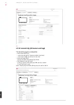
15.3 Connectivity (Ethernet settings)

The connectivity page has configuration
•  internet setting (ETH0).
  • connection needed for firmware update (local view).
  • connection to ABB cloud (cloud-connected)
•  Device settings (ETH1).
  • devices connected to gateway (local LAN).
•  Site Manager (Local view only).
  • settings for where Site Manager (5003) can be accessed.
  • firewall settings for port.
Note: changing any IP address settings requires device reboot

Summary of Contents for Ability

Page 1: ... USER MANUAL ABB AbilityTM Edge Industrial Gateway ...

Page 2: ...ABB ABILIT Y TM EDGE INDUSTRIAL GATEWAY 2 ...

Page 3: ...s document are the property of their respective owners This document is intended for system integrators skilled persons with a thorough knowledge in linking together physically or functionally different computing systems and software applications to operate as a coordinated whole in compliance with the applicable regulations Revision Market Release 02 2021 A Cloud connected added 04 2021 B ...

Page 4: ......

Page 5: ... 1 5 BASIC CONFIGURATION VIA PROVISIONING TOOL 1 6 ANNEX 2 WEB SERVER CONFIGURATION LOCAL VIEW 2 CONVENTIONS USED IN THIS DOCUMENT 7 MECHANICAL SPECIFICATIONS 1 2 ANNEX 1 ADDITIONAL I O MODULE 3 PRODUCT OVERVIEW 8 HOW TO INSTALL THE PRODUCT 1 3 DECLARATION OF CONFORMITY 4 NORMS AND CERTIFICATIONS 9 HOW TO SUPPLY POWER TO THE PRODUCT 1 4 MECHANICAL SPECIFICATIONS HOW TO INSTALL THE PRODUCT ...

Page 6: ......

Page 7: ...s 1 3 Cybersecurity 1 3 1 Disclaimer 1 3 2 TCP IP based protocols and used IP ports 1 4 Warning messages used in this document 1 4 1 Warning messages for harm to persons 1 4 2 Warning messages for damage to property 1 5 Warning power supply safety 1 6 Caution wireless safety ABB ABILIT Y TM EDGE INDUSTRIAL GATEWAY ...

Page 8: ...zards potentially created by electricity IMPORTANT In this manual the tasks are specifically indicated that can be performed by trained persons in an electrical environment All the remaining tasks described in the manual must be performed by trained persons in an electrical environment ABB accepts no liability for damage to property or personal injury due to failure to comply with the instructions...

Page 9: ...ks these risks comprise amongst other things the use of the product by unauthorized persons the alterations of its normal operation access to and modification of information The purchaser the installer or the final customer and person responsible for ensuring that safety warnings and notices are displayed and also that all the access points and operating devices are safely locked when the switchge...

Page 10: ...etwork are able to understand the communication exchange happening with the device 1 4 Warning messages used in this document 1 4 1 Warning messages for harm to persons To indicate an imminently hazardous situation which if not avoided will result in death or serious injury the following message is used DANGER Sign if necessary TEXT THAT EXPLAINS THE HAZARD AND THE CONSEQUENCES OF NOT AVOIDING IT ...

Page 11: ...ructions for safety installation and operation 2 Make sure your hands are dry 3 Make sure that all the cables used Are in good condition before using them Meet the product requirements and comply with the relevant standards and regulations 4 Position cables with care Do not position cables in places where they may be trampled or compressed by objects placed on them 5 Make sure that the power point...

Page 12: ......

Page 13: ... Conventions used in this document 2 1 Conventions for signal names 2 2 Conventions for signal types ABB ABILIT Y TM EDGE INDUSTRIAL GATEWAY 13 2 ...

Page 14: ...2 1 Conventions for signal names Convention Description GND Ground Active low signal Positive signal Positive signal in differential pair Negative signal Negative signal in differential pair 3 3 3 3 V signal level 5 5 V signal level NC No Connection Reserved Use is reserved to ABB ...

Page 15: ... 2 2 Conventions for signal types Convention Description I Signal is an input to the system O Signal is an output from the system IO Signal may be input or output P Power and Ground A Analog signal NC No Connection Reserved Use is reserved to ABB ...

Page 16: ...ABB ABILIT Y TM EDGE INDUSTRIAL GATEWAY 16 ...

Page 17: ...Y TM EDGE INDUSTRIAL GATEWAY 17 3 Product overview 3 1 Product description 3 2 Product models 3 3 Intended use and not allowed uses of the product 3 3 1 Intended use 3 4 Technical specifications 3 5 Product labels ...

Page 18: ...nnectivity 3 2 Product models The ABB Ability Edge Industrial Gateway has two models called local view and cloud connected The main difference between these models are supported interfaces and required connectivity The local view model can be used standalone inside private network without connection to cloud Differences can be seen on table below 3 3 Intended use and not allowed uses of the produc...

Page 19: ...ernet on RJ45 connectors USB 3x Host 2 0 noise and surge protected on Type A connectors Serial 1x RS 485 COM 0 Surge protected Insulated 1x RS 232 485 COM 1 Surge protected RS 485 termination and fail safe resistors Digital I O currently not supported 2x Digital Input 36 V 1 kV Optoinsulate 2x Digital Output 40 V AC DC 1 kV Optoinsulated 500 mA 1 kHz Max Switching Expansion Yes for Side Expansion ...

Page 20: ...formation NA versions only On the underside of the product Serial Number Label Serial number MAC ID number IMEI number CE mark EU versions only FCC mark EU versions only WEEE symbol EU versions only On the underside of the product Topside Label ABB logo ABB product name Interfaces name On the top side of the product ABB Serial Number Label ABB serial number Activation code On the left side of the ...

Page 21: ...ABB ABILIT Y TM EDGE INDUSTRIAL GATEWAY 21 3 ...

Page 22: ...ABB ABILIT Y TM EDGE INDUSTRIAL GATEWAY 22 4 ...

Page 23: ...ation statement 4 4 2 ISED Canada regulatory notices 4 4 3 RF radiation exposure statement 4 4 4 FCC class B digital device notice 4 4 5 ISED class B ddigital device notice 4 4 6 Labeling information 4 5 Restrictions on 5 GHz Wi Fi usage 4 5 1 EU restrictions on 5 GHz Wi Fi usage 4 5 2 FCC restrictions on 5 GHz Wi Fi usage 4 6 Antennas list 4 7 RoHS 3 compliance 4 8 REACH compliance 4 9 WEEE compl...

Page 24: ... the market of radio equipment For more information see Technical Specifications on page 19 4 2 1 Modification statement ABB has not approved any changes or modifications to this product by the user Any changes or modifications could void the user s authority to operate the product 4 3 FCC Marking Some versions of the product described in this document are FCC marked for more information see Techn...

Page 25: ...e following two conditions 1 This device may not cause harmful interference and this product must accept any interference received including interference that may cause undesired operation 2 This device must accept any interference received including interference that may cause undesired operation Note This equipment has been tested and found to comply with the limits for a Class B digital device ...

Page 26: ... the product labels Contains FCC ID RI7LE910NAV2 Contains FCC ID UKMMRG1012 Contains IC ID 5131A LE910NAV2 Contains IC ID 21442 MRG1012 CAN ICES 3 B NMB 3 B 4 5 Restrictions on 5 GHz Wi Fi Usage Channel Number Frequency MHz Europe ETSI North America FCC 36 5180 Indoor Usage Only Indoor Usage Only 40 5200 Indoor Usage Only Indoor Usage Only 44 5220 Indoor Usage Only Indoor Usage Only 48 5240 Indoor...

Page 27: ...tured in compliance with the Directive 2011 65 EU of the European Parliament and of the Council of 8 June 2011 on the restriction of the use of certain hazardous substances in electrical and electronic equipment 4 8 REACH compliance The product is certified according to the REACH Directive taking in account Substances of Very High Concern SVHC as specified in the list published by ECHA European Ch...

Page 28: ...ABB ABILIT Y TM EDGE INDUSTRIAL GATEWAY 28 5 ...

Page 29: ...IAL GATEWAY 29 5 Interfaces overview 5 1 Front side interfaces overview 5 2 Rear side interfaces overview 5 3 Service panel interfaces 5 4 Right side interface overview 5 5 Left side interface overview 5 6 LED indicators overview ...

Page 30: ...enna connector for 2 4 GHz Wi Fi Bluetooth 2 Main antenna connector for Internal Cellular Modem CELL MAIN only for ABB Ability Edge Industrial Gateway with 3G 3 Reserved 4 Diversity antenna connector for Internal Cellular Modem CELL DIV only for ABB Ability Edge Industrial Gateway with 3G 5 Antenna connector for 5 GHz Wi Fi 6 Not available 7 COM 0 1 connector 8 Digital I Os connector 1 2 3 4 5 6 7...

Page 31: ...es Layout Figure 4 Service Interfaces layout Ref Description 1 Ethernet ETH 1 connector Local LAN 2 Ethernet ETH 0 connector 3 USB 0 connector 4 USB 1 connector 5 Service Panel 6 Power IN connector Ref Description 1 MicroSD The MicroSD card holder is disabled 2 DIP switch for serial ports configuration 3 Pushbutton 4 Hardware reset push button 5 RTC backup supercap not removable 6 MicroSIM card ho...

Page 32: ...e Interface is as follows 5 5 Left side interface overview The Left Side Interface is as follows Ref Description 1 Expansion connector Ref Description 1 2 0 Host USB connector ready to interface optional USB storage Figure 5 Right Side Interfaces Layout Figure 6 Left Side Interface Layout 1 1 ...

Page 33: ... collection Green 3 LED 3 FW Update LED ON FW Update Error LED Blinking Update in progress Amber 4 LED 4 System Status LED OFF System OK LED ON Error Amber 5 N A ABB Ability Edge Industrial Gateway std version CELLULAR ABB Ability Edge Industrial Gateway with 3G LED ON Internal Cellular Modem ON LED Blinking Internal Cellular Modem connected to cellular network Green 6 POWER LED ON Product powered...

Page 34: ...6 ABB ABILIT Y TM EDGE INDUSTRIAL GATEWAY 34 ...

Page 35: ...nna requirements 6 2 4 Second antenna requirements for antenna diversity 6 2 5 The MicroSIM card holders 6 3 COM ports 6 3 1 Note for termination resistors for COM 1 in RS 485 mode 6 3 2 Note for fail safe resistors for COM 0 in RS 485 mode 6 3 3 Note for fail safe resistors for COM 1 in RS 485 mode 6 3 4 COM connector specifications 6 4 Ethernet ports 6 4 1 Ethernet specifications 6 4 2 ETH 0 1 c...

Page 36: ... Decryption using 64 128 and 256 Bit WEP TKIP or AES Keys Supports requirements for Wi Fi Protected Access WPA and WPA2 0 and IEEE Std 802 11i includes hardware accelerated Advanced Encryption Standard AES Designed to work with IEEE Std 802 1x IEEE Std 802 11d e h i k r PICS compliant New advanced co existence scheme with BT BLE 2 4 5 GHz Radio Internal LNA and PA Supports IEEE Std 802 11a 802 11b...

Page 37: ...ators impose restrictions Please consult with your carrier before considering single LTE antenna usage For optimum performance of the cellular interface ABB recommends the use of both CELL MAIN and CELL DIV antenna connectors 6 2 3 Main antenna requirements Telit LE910C1 EU Europe version Version Modem variant Technology ABB Ability Edge Industrial Gateway with 3G NA Telit LE910 NA1 North America ...

Page 38: ...card If you are using the holder on the top side of the circuit board To insert the MicroSIM card complete the following steps 1 Orient the MicroSIM card with the contacts facing the circuit board and the cut corner highlighted with the letter A facing the holder 2 Push the MicroSIM card in the holder To remove the MicroSIM card pull the eject lever use a pen tip to simplify the operation Feature ...

Page 39: ...standard axial resistor 120Ω if the application requires that If the ABB Ability Edge Industrial Gateway is not at the beginning or at end of the RS 485 chain two options are available Option 1 one pair of pins can remain not connected Option 2 one pair of pins can be used to connect the previous device of the chain and the other pair can be used to connect the following device of the chain 6 3 2 ...

Page 40: ...tion Electronics Co Ltd Part Number MC 1 5 10 STF 3 5 1847204 or equivalent Pin Signal Type Description 1 COM 0 D O COM port 0 RS 485 A D Line 2 COM 0 D O COM port 0 RS 485 B D Line 3 COM 0 IGND P Ground isolated 4 COM 0 D I COM port 0 RS 485 A D Line 5 COM 0 D I COM port 0 RS 485 B D Line 6 COM 1 TX D O COM port 1 RS 232 TX RS 485 B D Line 7 COM 1 RX D I COM port 1 RS 232 RX RS 485 A D Line 8 COM...

Page 41: ...cted Connector specifications RJ 45 socket Gender Female Mating connector specifications RJ 45 plug Gender Male Connector LEDs layout LEDs meaning Ref LED color LED meaning A Yellow Activity B Green Link Feature Description Network Standard IEEE 802 3u 10 100 BaseTX IEEE 802 3x full duplex flow control Speeds 10 100 BaseTX interfaces with MAC Notes The interfaces are noise and surge protected The ...

Page 42: ... USB 0 1 connectors specifications Connector Layout Connector Pinout Connector specifications USB Type A socket Gender Female Mating connector specifications USB Type A plug Gender Male 6 5 2 USB 2 connectors specifications Connector Layout Connector pinout Connector specifications USB Type A socket Gender Female Mating connector specifications USB Type A plug Gender Male Pin Signal Type Descripti...

Page 43: ...ABILIT Y TM EDGE INDUSTRIAL GATEWAY 43 6 6 6 Expansion connector The ABB Ability Edge Industrial Gateway provides on the right side an expansion connector with the following interfaces I O additional Module ...

Page 44: ...7 ABB ABILIT Y TM EDGE INDUSTRIAL GATEWAY 44 ...

Page 45: ...ABB ABILIT Y TM EDGE INDUSTRIAL GATEWAY 45 7 Mechanical specifications 7 1 Product mechanical dimensions 7 2 Mounting bracket mechanical dimensions ...

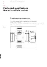
Page 46: ...ct mechanical dimensions The product electronics are housed in an ABS enclosure having the following dimensions 139 L x 115 W x 46 H mm Antennas Connectors and Mounting Bracket included All dimensions are in millimeters Mechanical specifications Figure 11 ...

Page 47: ...STRIAL GATEWAY 47 7 Figure 12 7 2 Mounting bracket mechanical dimensions The Mounting Bracket fastened on the bottom side of the ABB Ability Edge Industrial Gateway has the following dimensions ll dimensions are in millimeters ...

Page 48: ...8 ABB ABILIT Y TM EDGE INDUSTRIAL GATEWAY 48 ...

Page 49: ... or vice versa 8 2 1 How to replace the mounting bracket with the DIN rail mounting clip 8 2 2 How to replace the DIN rail mounting clip with the mounting bracket 8 2 3 Which screws are used with the mounting bracket or with the DIN rail mounting clip 8 3 How to install remove the product on from a DIN rail 8 3 1 How to install the product on a DIN rail 8 3 2 How to remove the product from a DIN r...

Page 50: ...Using the Mounting Bracket below How to Replace the Mounting Bracket with the DIN Rail Mounting Clip or Vice Versa on the next page How to Install Remove the Product on from a DIN Rail on page 53 8 1 1 How to install the product using the mounting bracket To install the product in place complete the following steps 1 See Mechanical Specifications on page 46 2 Use the 4 slots available on the Mount...

Page 51: ...he DIN rail mounting clip To replace the Mounting Bracket with the DIN Rail Mounting Clip on the product complete the following steps 1 Remove the 3 screws that hold the Mounting Bracket in place 2 Remove the Mounting Bracket and the 3 spacers H 4mm Ext diam 14mm Int diam 7mm 3 Place the DIN Rail Mounting Clip 4 Tighten the 3 screws removed at step 1 by applying a torque of 0 7 Nm 1 2 3 4 ...

Page 52: ... 4mm Ext diam 14mm Int diam 7mm and the Mounting Bracket 4 Tighten the 3 screws removed at step 1 by applying a torque of 0 7 Nm 8 2 3 Which screws are used with the mounting bracket or with the DIN rail mounting clip The 3 screws that hold in place the Mounting Bracket or the DIN Rail Mounting Clip have the following features Phillips type H cross flat countersunk head screw KA35x12 Fully threade...

Page 53: ...ook the upper mobile latches of the DIN Rail Mounting Clip on the upper edge of the DIN rail 2 Push the product against the DIN rail The lower latches of the DIN Rail Mounting Kit are locked on the DIN rail 8 3 2 How to remove the product from a DIN rail To remove the product from a horizontal DIN rail complete the following steps 1 Push downwards the upper mobile latches of the DIN Rail Mounting ...

Page 54: ...9 ABB ABILIT Y TM EDGE INDUSTRIAL GATEWAY 54 ...

Page 55: ...Y 55 9 How to supply power to the product 9 1 How to supply power to the product 9 1 1 Power IN connector and mating connector specifications 9 2 How to supply power and turn ON the product 9 3 How to trigger a hardware reset of the product ...

Page 56: ...the product The ABB Ability Edge Industrial Gateway provides the Power IN connector on the rear side Connector layout Connector Pinout Connector specifications Base strip Header Gender Male Type 3 pin 3 5 mm pitch Mating connector specifications Pluggable screw terminal block Gender Female Type 3 pin 3 5 mm pitch Example Manufacturer Phoenix Contact Part Number MC 1 5 3 STF 3 5 1847068 or equivale...

Page 57: ...eets the product requirements and complies with the relevant standards and regulations In case of uncertainties contact the ABB Technical Support Team for more information see How to Receive Technical Assistance 9 Connect power after the installation of the system has been completed 10 Never connect or disconnect the cables with the system or the external apparatus switched ON To supply power and ...

Page 58: ...1 0 ABB ABILIT Y TM EDGE INDUSTRIAL GATEWAY 58 ...

Page 59: ...ABB ABILIT Y TM EDGE INDUSTRIAL GATEWAY 59 1 0 How to maintain the product 10 1 How to safely remove the power supply 10 2 How to verify the installation of the product 10 3 How to clean the product ...

Page 60: ...from the product complete the following steps 1 Make sure your hands are dry 2 Turn OFF all the power supply sources 3 Disconnect all the cables 4 Make sure that all the circuits are discharged 10 2 How to verify the installation of the product To verify the installation of the product complete the following steps 1 Verify that the product is clean and not damaged 2 Verify that the LED indicators ...

Page 61: ...ABB ABILIT Y TM EDGE INDUSTRIAL GATEWAY 61 1 0 ...

Page 62: ...1 1 ABB ABILIT Y TM EDGE INDUSTRIAL GATEWAY 62 ...

Page 63: ...ess only for developer maintenance role 11 2 4 Adding Gateway hostname in client machine Windows 11 2 5 Accessing web server Local view 11 3 Ports and services 11 3 1 Ports 11 3 2 Device firewall 11 4 Time service 11 5 Remote syslog cloud connected 11 6 Security event monitoring Local view 11 6 1 Web server security events only for Edge Gateway 11 6 2 Daemon server security events 11 6 3 System se...

Page 64: ...esses communication ports and services Checking that the whole system has backups available from all applicable parts Collecting and storing backups of the system components and keeping those up to date Removing all unnecessary user accounts Defining password policies Changing default passwords and using strong passwords Checking that the link from substation to upper level system uses strong encr...

Page 65: ...al character Password must contain at least one numeric character Password must not exceed maximum 15 characters in length Account lockout policy In Web Server if a user failed to authenticate 5 times with incorrect password his account will be locked The locked period time is 15 minute and after elapsing this period User is again allowed to login into web server with correct password only Passwor...

Page 66: ...tenance role In ABB AbilityTM Edge Industrial Gateway SSH Secure Shell is NOT available for customer and is disabled This is available only to internal ABB Developers Maintenance Role users for debugging purpose Figure 21 Users and groups Users Figure 22 RBAC in Edge Gateway CRUD Create Read Update Delete CRU Create Read Update RU Read Update R Read Owner Manager Energy responsible Maintenance res...

Page 67: ...e https xxx elgateway abb local 5003 user computer needs to have host defined in hosts file This can be added with Administrative rights open the Notepad application Note this is optional device can be accessed by using IP address Navigate to below path C Windows System32 drivers etc Set All Files option and select hosts file and click Open Figure 23 Figure 24 ...

Page 68: ...r 11 2 5 Accessing web server Local view To access the web server user can use default IP address https 192 168 2 1 5003 Web server is only available in Local view version To access the web server user need to replace xxx below with the digits 4 to 7 for example A490050 000 0050 of the ABB Gateway Serial number https xxx elgateway abb local 5003 For example https 006 elgateway abb local 5003 Figur...

Page 69: ...ication protocol A communication protocol such as HTTP Modbus TCP signifies a set of rules to be used when sending receiving data over the network The table below list the ports used by various software processes in ABB AbilityTM Edge Industrial Gateway accomplishing a specific functionality Please note that WiFI Cellular is available only for certain models CRUD Create Read Update Delete CRU Crea...

Page 70: ...ial Gateway can be synchronized using NTP client to an NTP Server like Google NTP Server User can configure maximum three NTP Servers using Provisiong Tool By default one of the NTP time servers is shipped along with the ABB AbilityTM Edge Industrial Gateway with time google com User can configured all the three NTP Servers using CCT tool Time Synchronization is performed at every Powerup of ABB A...

Page 71: ...ers 11 6 Security event monitoring Local view Audit policies provide a means to monitor various actions by a user or a software process in ABB AbilityTM Edge Industrial Gateway The events generated by a specific audit policy denote a success or failed result for some action For Edge Gateway Owner Managers can download the event monitoring audit log files by navigating in Web Server to Settings Aud...

Page 72: ... 17 Update cellular settings Set cellular config and start service 18 Cellular enable Set cellular service enable 19 ssh enable Enable SSH Server 20 ssh disable Disable SSH Server Sr No Event Type Event Component Event Log Description 1 ADD Billing Billing Log for adding Billing details 2 UPDATE Billing Billing Log for updating Billing details 3 UPDATE device settings Devices Log for updating devi...

Page 73: ... the system s network environment auditd_rules_networkconfig_modification 10 alter process and session initiation information auditd_session 11 modify user group information auditd_rules_usergroup_modification 12 information on exporting to media auditd_export 13 modify the system s mandatory access controls auditd_MAC policy 11 6 3 System security events For system audit log events below are the ...

Page 74: ... as shown above in Figure 31 to start the firmware update process in Gateway A dialogue window will pop up to confirm to continue the process Once user press Yes button firmware update process is initiated in the Gateway The firmware update process in Gateway is initiated with Provisioning Tool sending the relevant information to the Gateway to download the firmware file from ABB hosted cloud With...

Page 75: ...tion via a network interface which should be connected to a secure network It is the sole responsibility of the person or entity responsible for network administration to ensure a secure connection to the network and to take the necessary measures such as but not limited to installation of firewalls application of authentication measures encryption of data installation of anti virus programs etc t...

Page 76: ...1 2 ABB ABILIT Y TM EDGE INDUSTRIAL GATEWAY 76 ...

Page 77: ...ABB ABILIT Y TM EDGE INDUSTRIAL GATEWAY 77 1 2 Annex 1 additional I O module 12 1 Product labels 12 2 Configuration ...

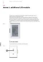
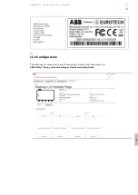
Page 78: ...alog ports Designed to be fitted to the side of the ABB Ability Edge Industrial Gateway it is rated for the same level of reliability and operating temperature range The digital section of I O module provides 6x isolated digital inputs and 4x isolated digital outputs while the analog section provides 2x protected current analog inputs and 2x protected voltage analog inputs 12 1 Product labels The ...

Page 79: ...B ABILIT Y TM EDGE INDUSTRIAL GATEWAY 79 1 2 12 2 Configuration The additional IO module can be confirued using Provision Tool Please refer to ABB Ability Energy and Asset Manager Cloud Provisioning Guide ...

Page 80: ...1 3 ABB ABILIT Y TM EDGE INDUSTRIAL GATEWAY 80 ...

Page 81: ...BILIT Y TM EDGE INDUSTRIAL GATEWAY 81 1 3 Declaration of conformity 13 1 CE Marking 13 2 WEEE compliance 13 3 RoHS 2 compliance 13 4 Electromagnetic compatibility 13 4 1 Electromagnetic compatibility for EU ...

Page 82: ...the product or within its literature indicates separate collection for this electrical and electronic equipment EEE that has been placed on the market after 2005 This product at the end of its life cycle must be collected separately and managed in accordance with the provisions of the current Directive on waste electrical and electronic equipment Because of the substances present in the product im...

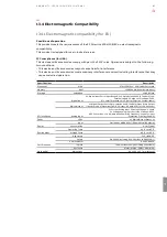
Page 83: ...erfaces Digital Input 6x Digital Input Ports Input Range 0 36V Optoisolation 5kV 2 7kV RMS Low Level Voltage 0 1V High Level Voltage 2 36V 0 1 Level Threshold 1V 2V Factory Option Customizable Digital Output 4x Digital Output Ports Optoisolation 5kV 2 7kV RMS Open Drain Output Transistors 60V Optorelay AC DC Output 0 5A MOSFET with 0 5A Fuses Analog Input 2x Current Analog Input Ports Input Range ...

Page 84: ...ABB ABILIT Y TM EDGE INDUSTRIAL GATEWAY 84 1 4 ...

Page 85: ...E INDUSTRIAL GATEWAY 85 1 4 Mechanical specifications How to install the product 14 1 I O module mechanical dimensions 14 2 How to install the product 14 2 1 How to attach I O module to ABB Ability Edge Industrial Gateway ...

Page 86: ...are housed in an ABS enclosure having the following dimensions 90 3 W x 59 0 L x 43 7 H mm The I O module enclosure is supplied on a mounting plate having the dimensions shown in the drawing Figure 34 below All dimensions are in millimetres Mechanical specifications How to install the product Figure 34 ...

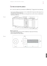
Page 87: ...he ABB Ability Edge Industrial Gateway as shown below using M2 5 x 5 CAP Head screw Screw the I O additional module module mounting plate to the same flat surface as the ABB Ability Edge Industrial Gateway Which screws are used The 4 screws are used to attach I O module to ABB Ability Edge Industrial Gateway M2 5 x 5 CAP Head Hexagon Socket Black A4 Stainless steel fully threaded Figure 35 Figure ...

Page 88: ...ABB ABILIT Y TM EDGE INDUSTRIAL GATEWAY 88 1 5 ...

Page 89: ...M EDGE INDUSTRIAL GATEWAY 89 1 5 Basic configuration via provisioning tool 15 1 Connect 15 2 Configuration 15 3 Connectivity Ethernet settings 15 4 Wifi settings Cloud connected 15 5 Cellular settings Cloud connected ...

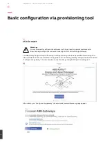
Page 90: ...Gateway The ABB Ability Edge Industrial Gateway is configured using windows based ABB Provisioning Tool After installation of the tool and after the login the user will find a gateway configuration button called Configure the gateway the user needs to connect to the gateway ETH0 port to configure it After clicking on Configure the gateway the automatic manual discovery page appears Basic configura...

Page 91: ...way discovery for provisioning If manual discovery is selected a dialog with the network scanning options pops up 15 2 Configuration After discover device can be selected and configuration page is opened The configuration page contains the following elements Time parameters manual NTP parameters automatic clock syncronization Maintenance Access Owner Details change owner or reset password ...

Page 92: ... setting ETH0 connection needed for firmware update local view connection to ABB cloud cloud connected Device settings ETH1 devices connected to gateway local LAN Site Manager Local view only settings for where Site Manager 5003 can be accessed firewall settings for port Note changing any IP address settings requires device reboot ...

Page 93: ...nection can be established also via WLAN network Settings can be changed using Connectivity page 15 5 Cellular settings Cloud connected Cloud connection can be establised also using cellular network Cellular connection requires SIM card to be inserted and data subscription enabled on the card ...

Page 94: ...ABB ABILIT Y TM EDGE INDUSTRIAL GATEWAY 94 1 6 ...

Page 95: ...ABB ABILIT Y TM EDGE INDUSTRIAL GATEWAY 95 1 6 Annex 2 Web server Configuration Local view 16 1 Configuration of the connections to web server 16 2 Navigation to web server ...

Page 96: ... gateway s ETH1 port to PC Laptop ETHERNET port C Edge Gateway default ETH1 IP address subnet mask is IP Address 192 168 2 1 Subnet Mask 255 255 255 0 D Setup ethernet at PC Laptop for local intranet access First connect the Edge Gateway to PC Laptop with ethernet cable In PC Laptop open the Network and Sharing Center and then open the Ethernet network as shown below Annex 2 Web server Configurati...

Page 97: ...t Status window E Install certificates configure hostname in windows machine please refer CSDG section no Include if any certificate needed for CCT F Link https xxx elgateway abb local where xxx is the last 3 digits of ABB device Serial number please check the label of the ABB Ability Edge Industrial Gateway for serial number G Web server default credentials to login into Web Server User ID OWNER ...

Page 98: ...available in this page c Data Analytics In this any device assets sensors can be grouped with Data Groups d Events a We can create combination of alerts for each device b We can get the events for the created alerts in above step c Latest recent event will be available on Dashboard directly e Settings a Site In this Site information can edited updated b Users and groups Users i Users Owner can add...

Page 99: ...ABB ABILIT Y TM EDGE INDUSTRIAL GATEWAY 99 1 6 ...

Page 100: ...representations or warranties of any kind expressed or implied about the completeness accuracy reliability suitability or availability with respect to the information products services or related graphics contained in the document for any purpose Any reliance placed on such information is therefore strictly at your own risk ABB reserves the right to discontinue any product or service at any time C...

Reviews: