


Assembly Instructions / A100-L
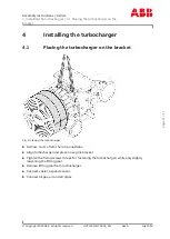
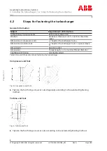
4 Installing the turbocharger / 4.2 Steps for fastening the turbochar-
ger
© Copyright 2020 ABB. All rights reserved.
HZTL455311P0002_EN
Rev.A
July 2020
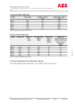
Torque-controlled tightening
Product
Thread size
Height a of foot
[mm]
Tightening torque
[Nm]
A165-L
M22
86
440
A170-L
M27
100
830
A175-L
M30
120
1100
A180-L
M33
136
1500
A185-L
M39
151
2500
A190-L
M42
167
3100
Table 6: Tightening torques (foot screws)
Angle-controlled tightening
Product Thread size
Height a
foot
[mm]
Pre-tightening
torque
[Nm]
Tightening
angle
height a
[DEG]
Additional
tightening angle for
every 10 mm of ad-
ditional screw
length b
[DEG]
A165-L
M22
86
120
30
3.7
A170-L
M27
100
220
30
3.1
A175-L
M30
120
300
30
2.6
A180-L
M33
136
400
35
2.6
A185-L
M39
151
600
35
2.4
A190-L
M42
167
700
35
2.2
Table 7: Tightening angle (foot screws)
Pinning of turbocharger feet with positioning pins
If the turbocharger is pinned at its feet, one pin hole per foot must be used.
Page
13
/
17
Summary of Contents for A100-L Series
Page 2: ......


