


- 25 -
. . . ADDENDUM FOR "METERS" OPTION OF THE TRANSMITTERS
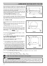
The calibration can be performed in output current or percentage,
or in process engineering units (see fig. 2).
Proceed as follows:
A) OUTPUT CURRENT (4
÷
20 mA)
1) The switches from SW1 to SW6 must be positioned as
follows :
ON - OFF - ON - OFF - ON - OFF
2) Set the output current of the current generator to 4 mA,
reading it on the milliammeter or 1 V. on the DVM.
Alternatively force, using the "Loop Test" procedure on
the Hand Held Communicator, the output of your Smart
transmitter to 4 mA.
3) Adjust the zero trimmer (Z) to read approximately 4.00
4) Set the output current to 19.9 mA, reading it on the
milliammeter, or 4.975 V. on the DVM. Alternatively
force the output of your Smart transmitter to 19.9 mA
checking for this value in the Hand Held Communicator.
5) Adjust the span trimmer (S) to read approximately 19.90.
6) Repeat the points 2) 3) to read exactly 4.00 (
±
0.1)
7) Repeat the points 4) 5) to read exactly 19.90 (
±
0.1)
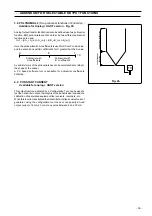
8) Fit the "mA" unit label in the right recess below the
indication.
B) OUTPUT PERCENTAGE (0
÷
100%)
1) The switches from SW1 to SW6 must be positioned as
follows :
ON - OFF - ON - ON - OFF - ON
2) Set the output current of the current generator to 4 mA,
reading it on the milliammeter or 1 V. on the DVM.
Alternatively force, using the "Loop Test" procedure on
the Hand Held Communicator, the output of your Smart
transmitter to 4 mA.
3) Adjust the zero trimmer (Z) to read approximately 00.0
4) Set the output current to 20 mA, reading it on the
milliammeter, or 5 V. on the DVM. Alternatively force the
output of your Smart transmitter to 20 mA checking for
this value in the Hand Held Communicator.
5) Adjust the span trimmer (S) to read approximately 100.0.
6) Repeat the points 2) 3) to read exactly 00.0 (
±
0.1)
7) Repeat the points 4) 5) to read exactly 100.0 (
±
0.1)
8) Fit the "%" unit label in the right recess below the
indication.
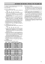
C) ENGINEERING UNITS
The switches must be positioned as follows:
-1999
÷
-1000
-1000
÷
0
0
÷
1000
1000
÷
1999
OFF
ON
OFF
ON
OFF
OFF
ON
ON
SW1 SW2
For ZERO adjustment, between
100
÷
1000
1000
÷
2000
2000
÷
3000
3000
÷
3998
ON
OFF
ON
OFF
ON
ON
OFF
OFF
SW3 SW4
4.00
÷
19.99
40.0
÷
199.9
400
÷
1999
OFF
ON
OFF
ON
OFF
OFF
SW5 SW6
For SPAN adjustment, between
For DECIMAL POINT position, like
Then proceed as follows:
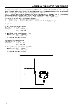
1) Set the output current of the current generator to 4 mA on
the milliammeter or 1 V. on the DVM. Alternatively, using
the "Loop Test" procedure on the Hand Held
Communicator, force the output of your Smart transmitter
to 4 mA.
2) Adjust the zero trimmer (Z) to read approximately the
lower range value (LRV) on the digital meter.
3) Set the output current to 20 mA, on the milliammeter or
5 V. on the DVM. Alternatively force the output of the
transmitter to 20 mA using the Hand Held Communicator.
4) Adjust the span trimmer (S) to read approximately the
upper range value (URV) on the digital meter.
5) Repeat the points 1) 2) to read exactly the LRV (
±
0.1) .
6) Repeat the points 3) 4) to read exactly the URV (
±
0.1)
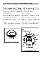
7) Complete the calibration procedure by fitting the
multiplication factor label (if any) in the left recess below
the display and the engineering unit label in the right
recess (see fig. 2).


