
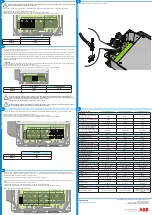
13.
Ground connection
WIND INTERFACE BOX4000-7200-Quick Installation Guide EN-RevA
EFFECTIVE 2014-04-02
© Copyright 2014 ABB. All Rights Reserved.
Specifications subject to change without notice.
9.
Input
connection AC
10.
Diversion Load resistor
12.
Tachometer output
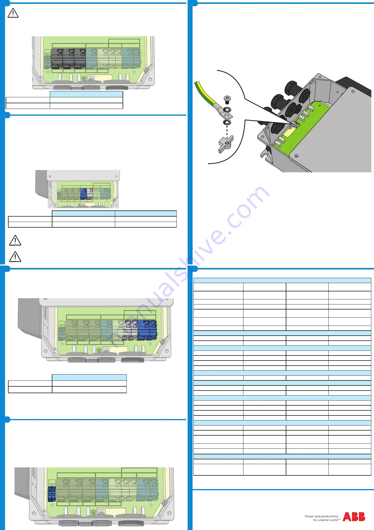
14.
Characteristics and technical data
Output connection (DC)
11.
The purpose of the diversion/dump load is to help keep the turbine under control under two conditions without triggering the external braking systems (both
electrical and mechanical). Those conditions are:
- Inverter disconnected from the electrical grid. Without the inverter on the grid, the turbine would turn freely, unloaded. This calls for a method to avoid runaway
and keep the turbine within its specified operating range, reducing the need to invoke mechanical protection mechanisms (disc brakes, pitch control, etc).
- Exceeding the maximum power of the inverter. At sites where the maximum power rating of the inverter will be exceeded only a few times per year, it’s pos-
sible to employ a dump load instead of an inverter with a higher power rating. During strong winds, the excess power that can’t be handled by the inverter is
shunted to the resistive load.
CONNECTION
To connect the two wires, coming from Diversion load resistor to the terminal requires releasing the terminal spring clamp. This is accomplished as follows:
1) Insert the flat blade of a screw driver into the connector release hole.
2) While holding the release open, insert the appropriate wire into the connector hole marked CLAMP
3) Hold the wire in place in the clamp and remove the screwdriver from the RELEASE hole to clamp the wire in the terminal.
WIRE GAUGE
RESISTANCE VALUE
MINIMUM
10 AWG
320 ohm
MAXIMUM
6 AWG
-
The correct sizing of the dump load resistor is dictated by the characteristics of the individual site and the characteristics of the
individual wind turbine, and is beyond the scope of this guide. The determination of the resistor value (ohms) and dissipation rating
(watts) is the resposnsibility of the wind turbine system designer or the customer.
Remember that the values IABR(max) and IDC(max) must never exceeded.
The Wind Interface may not always be able to prevent runaway (for instance, if the generator fails), therefore it is necessary to have an
external Safety Brake circuit, electrical and/or mechanical, that brakes the system.
To connect the two wires, coming from DC side of inverter, to the terminal requires releasing the terminal spring clamp. This is accomplished as follows:
1) Insert the flat blade of a screw driver into the connector release hole.
2) While holding the release open, insert the appropriate wire into the connector hole marked CLAMP
3) Hold the wire in place in the clamp and remove the screwdriver from the RELEASE hole to clamp the wire in the terminal.
WIRE GAUGE
MINIMUM
10 AWG
MAXIMUM
10 AWG
Tachometer output (WIND SPEED connector) is an open collector source. The generated pulse train has frequency identical to the generator frequency.
Max pull up voltage = 24Vdc; zero level = 1.4Vmax; max current = 1mA. The pulse train is generated from two of the wind turbine input phases (1 and 2). A
hardware filtering optimizes the frequency reading in the range 5-200Hz.
This link is mandatory if in the inverter is uploaded a power curve defined in term of frequency.
To connect the two wires, coming from +/- WT connector of inverter, to the terminal requires releasing the terminal spring clamp. This is accomplished as
follows:
1) Insert the flat blade of a screw driver into the connector release hole.
2) While holding the release open, insert the appropriate wire into the connector hole marked CLAMP
3) Hold the wire in place in the clamp and remove the screwdriver from the RELEASE hole to clamp the wire in the terminal.
Refer to the inverter Quick intallation guide for more details.
WIND INPUT
1
2
3
BRAKE
BULK OUT
+
-
WIND
SPEED
+ -
+
-
WIND INPUT
1
2
3
BRAKE
BULK OUT
+
-
WIND
SPEED
+ -
+
-
WIND INPUT
1
2
3
BRAKE
BULK OUT
+
-
WIND
SPEED
+ -
+
-
Contact us
www.abb.com/converters-inverters
Table: Technical Data
4000-WIND-INTERFACE-EU
7200-WIND-INTERFACE-EU
PVI-7200-WIND-INTERFACE
Input side
AC input voltage range (no damage)
(Vacd,min...Vacd,max)
0...400 V
0...400 V
0...400 V
Operating AC input voltage range (Vac-
min...Vacmax)
35...400 V
35...400 V
0...400 V
Operating frequency range (fmin...fmax)
0...600 Hz
0...600 Hz
0...600 Hz
Maximum AC input current (Iacmax)
16.6 A
16.6 A
16.6 A
Maximum current in auxiliary brake
(diversion load) resistor (IABR,max)
6 A
20 A
20 A
DC voltage range in auxiliary brake (diver-
sion load) resistor (VABRmin...VABRmax)
fixed at 530 V
fixed at 530 V
fixed at 530 V
Wiring termination
Push Wire
Push Wire
Push Wire
Input protection devices
Overvoltage protection type
Varistors, 3
Varistors, 3
Varistors, 3
Input fuse size
3 x 6 A
3 x 20 A
3 x 20 A
Output side
Maximum output power (Pdcmax)
4 kW
7.2 kW
7.2 kW
Output voltage range (Vdc,min...Vdc,max)
0...600 V
0...600 V
0...600 V
Maximum output current (Idc,max)
6 A
20 A
20 A
Wiring termination
Push Wire
Push Wire
Push Wire
Output protection devices
Overvoltage protection type
No
No
No
Operating performance
Peak efficiency (ηpeak)
99.4%
99.4%
99.4%
Stand-by consumption
< 3 W
< 3 W
< 3 W
Environmental
Ambient air operating temperature range
-25...+55°C (-13...131°F)
-25...+55°C (-13...131°F)
-13°F to 131°F (-25°C to +55°C)
Relative humidity
0...100 % condensing
0...100 % condensing
0...100 % condensing
Acoustic noise emission level
<40 db(A)@1m
<40 db(A)@1m
<40 db(A)@1m
Maximum altitude without derating
2000 m (6560 ft)
2000 m (6560 ft)
6560 ft (2000 m)
Physical
Enclosure rating
IP 65
IP 65
NEMA 4X
Cooling
Natural
Natural
Natural
Dimension (H x W x D)
252 mm x 287 mm x 85.7 mm (9.9
in x 11.3 in x 3.37 in)
252 mm x 287 mm x 85.7 mm (9.9
in x 11.3 in x 3.37 in)
9.9 in x 11.3 in x 3.37 in, (252 mm
x 287 mm x 85.7 mm)
Weight
1.8 kg (4.0 lb)
1.8 kg (4.0 lb)
4.0 lb (1.8 kg)
Mounting system
Wall mount
Wall mount
Wall mount
Safety
Safety approval
CE
CE
cCSAus
Safety and EMC standard
EN 50178, EN 61000-6-2
EN 50178, EN 61000-6-2
UL Std. No. 1741 - 2nd Edition,
IEEE1547, CSA C22.2 107.1-
01-2001
Wiring must be done with the inverter disconnected from the grid. Both the grid-side switch (S2) and the turbine side switch (S1) must be
open. The turbine itself must be parked and in safty mode
To connect the three wires, coming from generator, to the terminal requires releasing the terminal spring clamp. This is accomplished as follows:
1) Insert the flat blade of a screw driver into the connector release hole.
2) While holding the release open, insert the appropriate wire into the connector hole marked CLAMP
3) Hold the wire in place in the clamp and remove the screwdriver from the RELEASE hole to clamp the wire in the terminal.
WIRE GAUGE
MINIMUM
10 AWG
MAXIMUM
6 AWG
The equipment ground connection to wind box is show below:
WIND INPUT
1
2
3
BRAKE
BULK OUT
+
-
WIND
SPEED
+ -
+
-


