54 SBC347A 3U VPX Single Board Computer
Publication No. 500-9300527837-000 Rev. A.0
5.18.1 BIT LEDs (DS401 to DS404)
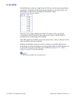
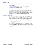
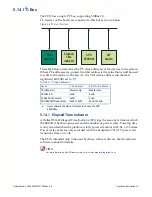
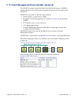
The SBC347A has four software-controlled LEDs, to reflect the status of BIT or
other boot software. When used by BIT, the LEDs have the following meanings:
The BMM controls the BIT Fail LED, which is powered from the auxiliary power
supply so that it can remain lit even when the main power supplies are not active
or have failed.
TIP
The BIT LED is lit by default and relies on the BMM, BIT, or another operating system to switch it
off. So, as well as indicating a BIT failure, it can also indicate a problem with the BMM or failure to
run an operating system.
The two yellow and one green LEDs are unlit after reset and are driven by the
FPGA under software control.
When BIT is installed on the SBC347A, the red LED either shows that BIT has not
yet run (straight after a reset) or has run but failed. The yellow LEDs show
progress through BIT, and so may provide information for debugging purposes in
the event of failure. The green LED shows that BIT has passed.
The BIT_FAIL~ (
) backplane signal is driven active low using an open-drain
driver when the red LED is lit.
When BIT is not installed on the SBC347A, other OSs may use the BIT status LEDs
to indicate status. See the relevant software manual for more information.
5.18.2 Board Reset LED (DS405)
The platform reset signal drives this red LED to show that the SBC347A is in reset.
There are several reset sources that could cause the platform reset signal to assert.
This LED also indicates the status of the CPU Catastrophic Error signal. When this
signal is asserted (indicating that a non-recoverable error has occurred), the LED
will flash at approximately 4 Hz.
This LED also indicates the status of the CPU solder ball daisy-chain. When the
chain is broken, the LED will flash at approximately 2 Hz, indicating that the CPU
may not be soldered to the board properly. If this occurs, contact Technical
Support for more information (see
Technical Support Contact Information
Table 5-16 BIT LED Meanings
LEDs
Color
Meaning When Lit
DS401
Red
BIT Fail
DS404
Green
BIT Pass
DS403
Yellow
BIT status 2 (see BIT documentation)
DS402
Yellow
BIT status 1 (see BIT documentation)
Table 5-17 BIT Status LED Meanings
BIT Fail LED
(DS401)
BIT Passed LED
(DS404)
Status
On
Off
BIT not yet run (Reset state) or BIT failed
Off
On
BIT complete and passed


