Publication No. HRMCP9 Rev. B
Interfaces 43
Table 5-8 COM1 Pin Assignments
Name RS232
Name RS422/485
P2201
DCD
TXD-
1
DSR
TXD+
6
RXD
RTS-
2
RTS
RTS+
7
TXD
CTS+
3
CTS
CTS-
8
DTR
RXD+
4
RI
RXD-
9
GND
GND
5
5.2.8
VGA Interface P4200
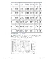
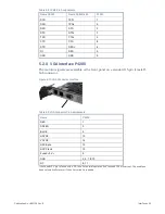
The monitor signals are available at the front panel on a standard 15-pin female D-
Sub connector.
Figure 5-10 VGA Connector Location
Table 5-9 VGA Connector Pin Assignments
Name
P4200
RED
1
GREEN
2
BLUE
3
HSYNC
13
VSYNC
14
DDC-Data
12
DDC-Clock
15
Fused +5 V
a
9
GND
5, 6, 7, 8, 10
NC
4, 11
a
the Fused +5 V pin is fused with a 2 A fuse. For normal operation don’t exceed 100 mA current. The used fuse
does automatically recover if the over current is resolved.


