background image


22


1.


Set the 

ON/OFF

 power Switch to 

"

OFF

". 

2.


Turn the regulator knob 

counterclockwise to set the outlet 

pressure to zero. 

3.


Remove the air tool or accessory. 

4.


Place a suitable container under 

the drain valve to catch discharge. 

5.


Pull ring on safety valve allowing air 

to bleed from the tank until tank 

pressure is approximately 20 psi. 

Release safety valve ring. 

6.


Drain water from air tank 

unthreading the Drain Valve two or 

three turns 

ONLY

7.


After the water has been released, 

close the drain valve

.   

CAUTION!


Do not open the 

Drain Valve so that more than four 

threads . 


The air compressor can now be stored. 


TO REPLACE REGULATOR


WARNING: 

Risk of unsafe 

operation. Unit cycles automatically 

when power is on. 

When performing maintenance, you 

may be exposed to voltage sources

compressed air, or moving parts. 

Personal injuries can occur. Before 

performing any maintenance or repair, 

disconnect power source from the 

compressor and bleed off all air 

pressure and allow the air compressor 

to cool.


1.


Release all air pressure from air tank.   

See To Drain Tank in the Maintenance 

section. 

2.


Unplug unit. 

3.


Remove the console cover. 

4.


Using an adjustable wrench remove 

the safety valve from the regulator 

manifold. 

5.


Remove the hose by removing the 

hose clamp.   

NOTE: 

The hose clamp is not 

reusable. You must purchase a new, 

standard hose clamp at a local 

hardware store. 

6.


Remove pump mounting screws 

securing pump (one on each side). 

7.


Carefully slide pump from brackets 

and out of the way. 

8.


Using an adjustable wrench remove 

the regulator manifold . 

9.


Apply pipe sealant to new regulator 

manifold and assemble, tighten with 

wrench. 

10.


Reapply pipe sealant to safety valve. 

11.


Reassemble all components in 

reverse order of removal. Make sure 

to orient gauges to read correctly 

and use wrenches to tighten all 

components. 


Summary of Contents for A12101

Page 1: ...l before assembling operating and maintaining this unit You are responsible for operating the product properly safely Version V1 20171222 A A V I X O U T D O O R S FOR SERVICE CALL USA 1 866 591 8921...

Page 2: ...l cannot cover all possible conditions and situations that may occur It must be understood by the operator that common sense and caution are factors which cannot be built into this product but must be...

Page 3: ...pressor use and care a Do not use the compressor if the power Switch does not turn it on and off Any compressor that cannot be controlled with the power Switch is dangerous and must be repaired b Disc...

Page 4: ...hever is greater 10 Industrial applications must follow OSHA guidelines 11 Maintain labels and nameplates on the compressor These carry important safety information If unreadable or missing contact ou...

Page 5: ...w the compressor to operate unattended HOW TO PREVENT IT Always remain in attendance with the product when it is operating Always turn off and unplug unit when not in use Do not leave compressor unatt...

Page 6: ...k of injury to consumers Your compressor air tank must be removed from service by the end of the year shown on your tank warning label The following conditions could lead to a weakening of the air tan...

Page 7: ...TO PREVENT IT Never operate the compressor outdoors when it is raining or in wet conditions Never operate compressor with protective covers removed or damaged 2 WHAT CAN HAPPEN Repairs attempted by un...

Page 8: ...parts such as the pulley flywheel and belt can cause serious injury if they come into contact with you or your clothing HOW TO PREVENT IT Never operate the compressor with guards or covers which are d...

Page 9: ...der some conditions and duration of use noise from this product may contribute to hearing loss HOW TO PREVENT IT Always wear proper hearing protection during use 27 AIR RECEIVER Over pressurizing the...

Page 10: ...esulting in power loss to the motor and overheating Instead of using an extension cord increase the working reach of the air hose by attaching another length of hose to its end Attach additional lengt...

Page 11: ...YOUR UNIT Compare the illustrations with your unit to familiarize yourself with the location of various controls and adjustments Save this manual for future reference 1 Power Switch 2 Reset Button 3...

Page 12: ...for this fan to blow air through the vent holes in large amounts You know that the cooling system is working when air is being expelled Air Compressor Pump not shown Compresses air into the air tank...

Page 13: ...cated at least 12 30 5 cm away from the wall or other obstructions that will interfere with the flow of air The air compressor pump and shroud are designed to allow for proper cooling The ventilation...

Page 14: ...ces Do not modify the plug provided if it will not fit the outlet have the proper outlet installed by a qualified electrician 7 Improper connection of the equipment grounding conductor can result in a...

Page 15: ...ilter or a dryer all not provided as shown on Figure A and Figure B Consult your air tool s manual for needed accessories A Portable Air Supply Setup A Air Hose Connects air to tool B Filter Prevents...

Page 16: ...of use H Air Hose Connects air to tool I Filter Prevents dirt and condensation from damaging tool or workpiece J Regulator Adjusts air pressure to tool K Lubricator optional For air tool lubrication L...

Page 17: ...ies The regulator outlet pressure must never exceed the maximum pressure rating NOTE Risk of property damage Compressed air from the unit may contain water condensation and oil mist Do not spray unfil...

Page 18: ...pressure switch The Compressor will turn on automatically when the air pressure drops to 85 PSI and will turn off automatically when the air pressure reaches 100 PSI WARNING TO PREVENT SERIOUS INJURY...

Page 19: ...otor Overload Protector Automatic Shut Off System not shown The motor has a thermal overload protector If the motor overheats for any reason the overload protector will shut off the motor The motor mu...

Page 20: ...mpressor NOTE The environment in which the compressor is used and the frequency of use can affect how often you will need to check the Air Compressor components and perform maintenance procedures DAIL...

Page 21: ...Operation Air tanks contain high pressure air Keep face and other body parts away from outlet of drain Use ANSI Z87 1 eye protection CAN CSA Z94 3 when draining as debris can be kicked up into face W...

Page 22: ...arts Personal injuries can occur Before performing any maintenance or repair disconnect power source from the compressor and bleed off all air pressure and allow the air compressor to cool 1 Release a...

Page 23: ...ee To Drain Tank under Maintenance WARNING Water will condense in the air tank If not drained water will corrode and weaken the air tank causing a risk of air tank rupture 3 Protect the electrical cor...

Page 24: ...urely Disconnect the other electrical appliances from circuit or operate the compressor on its own branch circuit Check the extension cord Check wiring connection inside terminal box 3 Incorrect power...

Page 25: ...t start up again on its own See Motor Overload Protector in OPERATION section contact a trained service technician 5 Loose fittings 5 Reduce air pressure then check all fittings with a soap solution f...

Page 26: ...lace with wider hose and or hose connections 9 High altitude reducing air output 9 Higher altitudes require compressors with greater output 10 Pressure switch adjusted too low or 10 Make necessary adj...

Page 27: ...ion cord or eliminate extension cord See Recommended Wire Gauge for Extension Cords 6 Dirty compressor head cylinder intercooler 6 Clean with compressed air 7 Operating pressure too high 7 Reduce oper...

Page 28: ...Excessive tank pressure safety valve pops off 1 Safety valve needs service 1 Pull on test ring of safety valve If it still pops replace 2 Pressure switch does not shut off motor when compressor reache...

Page 29: ...01 44 13 Plain Washer 1 A12101 13 45 Bolt 4 A12101 45 14 Fan 1 A12101 14 46 Bolt 3 A12101 46 15 Screw 2 A12101 15 47 Plain Washer 3 A12101 47 16 Ground Wire 1 A12101 16 48 Pressure Switch 1 A12101 48...

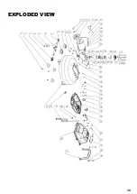
Page 30: ...30 EXPLODED VIEW...

Reviews: