background image


78 

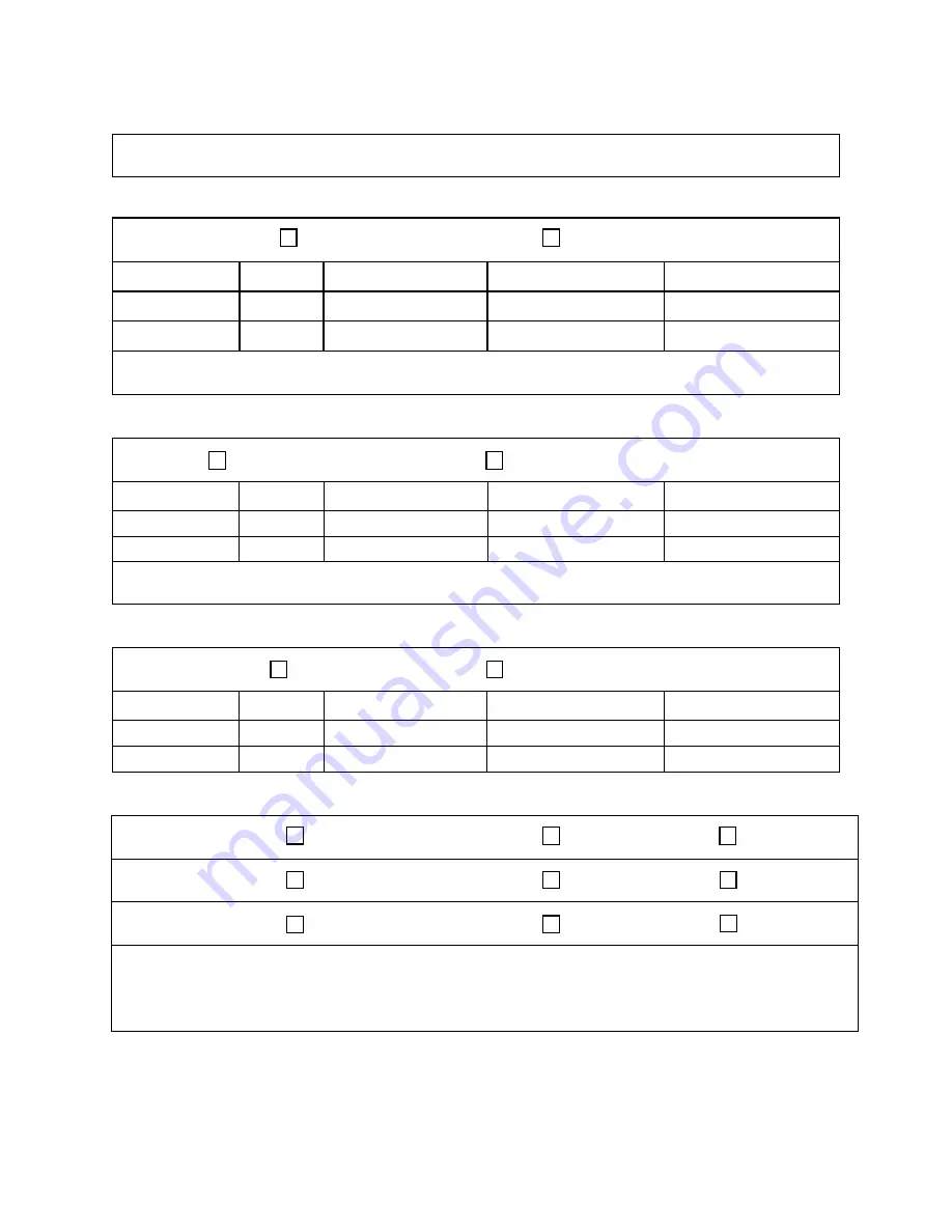
Ambient Temperature 


Ambient Dry Bulb Temperature ________°F 


Ambient Wet Bulb Temperature ________°F 


Supply Fan Assembly 


Alignment  


Check Rotation  


Nameplate Amps________ 


Number 

hp 

L1 

L2 

L3 


VFD Frequency________________


VAV Controls_________________ 


Power Exhaust Fan Assembly 


Alignment  


Check Rotation  


Nameplate Amps________ 


Number 

hp 

L1 

L2 

L3 


VFD Frequency________________


VAV Controls_________________ 


Energy Recovery Wheel Assembly 


Wheels Spin Freely  


Check Rotation  


FLA ________ 


Number 

hp 

L1 

L2 

L3 


Dampers 


OA Operation Check  


Damper Wiring Check  


Gears Check  


RA Operation Check  


Damper Wiring Check  


Gears Check  


EA Operation Check  


Damper Wiring Check  


Gears Check  


Damper Actuator Type:__________________________________________________________ 


Economizer Changeover Type and Operation:_______________________________________ 


Summary of Contents for V3-A

Page 1: ... FOR YOUR SAFETY Do not store or use gasoline or other flammable vapors and liquids in the vicinity of this or any other appliance WARNING WARNING QUALIFIED INSTALLER Improper installation adjustment alteration service or maintenance can cause property damage personal injury or loss of life Startup and service must be performed by a Factory Trained Service Technician A copy of this IOM should be k...

Page 2: ...orator Coil 29 Thermal Expansion Valve 29 Hot Gas Reheat 29 Hot Gas Bypass 29 Purge Circuit 30 Energy Recovery Units 30 Initial Mechanical Check and Setup 31 Routine Maintenance and Handling 32 Cleaning 32 Wheel Drive Components 33 Startup Procedure 34 Service 35 Electrical 37 Gas Heating 40 Unit Location and Clearances 40 Condensate Drain Piping 41 Condensate Neutralization 41 General Venting 42 ...

Page 3: ...ter Preheating Operation 58 Electric Heating Operation 58 Gas Heater Operation 58 Gas Heater Operating and Safety Instructions 59 Shutdown 59 Maintenance 63 DX Cooling 63 Condensate Drain Pans 63 Gas Heating 64 Furnace Maintenance 65 E Coated Coil Cleaning 67 Winterizing Coils 69 Supply Fans 69 Phase and Brownout Protection Module 70 Filter Replacement 72 Replacement Parts 72 AAON Technical Suppor...

Page 4: ...ation 60 Table 19 Gas Heater LED Diagnostics 62 Table 20 Gas Heater Troubleshooting Guide 63 Table 21 V3 Series E Cabinet Pre Filters 73 Table 22 V3 Series A Cabinet Unit Filters 74 Table 23 V3 Series B Cabinet Unit Filters 74 Table 24 V3 Series C Cabinet Unit Filters 75 Table 25 V3 Series D Cabinet Unit Filters 75 Table 26 V3 Series Energy Recovery OA Filters Feature 13 A V 75 Figures Figure 1 Lo...

Page 5: ...ctions 38 Figure 29 Gas Heat Condensate Trap 41 Figure 30 Condensate Neutralizer Kit 42 Figure 31 Open Combustion Venting 44 Figure 32 Separated Combustion Venting 45 Figure 33 Sediment Trap for Gas Heat 48 Figure 34 Typical wiring diagram with EC motor 50 Figure 35 Shows the jumper that is to be removed jumped between 9 and GS 51 Figure 36 Potentiometer 51 Figure 37 Gas Heater Instructions 55 Fig...

Page 6: ...r statements are given to prevent actions that will result in equipment damage property damage severe personal injury or death ELECTRIC SHOCK FIRE OR EXPLOSION HAZARD Failure to follow safety warnings exactly could result in dangerous operation serious injury death or property damage Improper servicing could result in dangerous operation serious injury death or property damage Installation and ser...

Page 7: ...rk with live electrical components Only a qualified licensed electrician or individual properly trained in handling live electrical components shall perform these tasks Standard NFPA 70E an OSHA regulation requiring an Arc Flash Boundary to be field established and marked for identification of where appropriate Personal Protective Equipment PPE be worn should be followed WARNING ROTATING COMPONENT...

Page 8: ...mage to the unit do not use acidic chemical coil cleaners Do not use alkaline chemical coil cleaners with a pH value greater than 8 5 after mixing without first using an aluminum corrosion inhibitor in the cleaning solution WARNING CAUTION Do not use oxygen acetylene or air in place of refrigerant and dry nitrogen for leak testing A violent explosion may result causing injury or death WARNING Alwa...

Page 9: ...th a pad lock always re install the nut bolt after closing the door CAUTION PVC Polyvinyl Chloride and CPVC Chlorinated Polyvinyl Chloride are vulnerable to attack by certain chemicals Polyolester POE oils used with R 410A and other refrigerants even in trace amounts in a PVC or CPVC piping system will result in stress cracking of the piping and fittings and complete piping system failure CAUTION ...

Page 10: ...stall and operate furnace within the intended airflow range temperature rise range and duct system external static pressure ESP as specified on the unit nameplate 10 The supply and return air ducts must be derived from the same space It is recommended ducts be provided with access panels to allow inspection for duct tightness When a down flow duct is used with electric heat the exhaust duct should...

Page 11: ...D Up to 6 000 cfm E Up to 10 000 cfm UNIT ORIENTATION R Right Hand Connections L Left Hand Connections REVISION B Second Revision VOLTAGE 1 230V 1Φ 60Hz 2 230V 3Φ 60Hz 3 460V 3Φ 60Hz 4 575V 3Φ 60Hz 8 208V 3Φ 60Hz 9 208V 1Φ 60Hz CORROSION PROTECTION 0 None A Interior Corrosion Protection Model Option A COOLING A1 COOLING TYPE 0 No Cooling 1 R 410A DX Cooling 2 Chilled Water Cooling A2 COOILNG ROWS ...

Page 12: ...R 108MBH input J 63 kW 47 3 kW 208V OR 120MBH input K 70 kW 52 5 kW 208V L 77 kW 57 8 kW 208V OR 160MBH input M 84 kW 63 0 kW 208V B3 HEATING STAGES 0 No Heating 1 1 Stage 2 2 Stage 3 3 Stage 4 4 Stage A Modulating 3 1 96 Efficient Counter Flow D 2 Stage 96 Efficient Counter Flow G 4 Stage 96 Efficient Counter Flow S Modulating SCR Electric B3 HEATING STAGES Continued F Single Serpentine 12 fpi H ...

Page 13: ...Supply Air Firestat C Return Air Smoke Detector D Options A B E Options A C F Options B C G Options A B C H Remote Safety Shutdown Terminals J Energy Recovery Wheel Rotation Detection K Options A H L Options A J M Options B H N Options B J P Options C H Q Options C J R Options H J S Options A B H T Options A B J U Options A C H V Options A C J Feature 4 ADDITIONAL CONTROLS Continued W Options A H ...

Page 14: ... Standard None A 2 Pleated 30 Eff MERV 10 B 4 Pleated 30 Eff MERV 10 C 4 Pleated 65 Eff MERV 11 D 4 Pleated 85 Eff MERV 13 E 4 Pleated 95 Eff MERV 14 F 2 Pleated 30 Eff MERV 10 4 Pleated 30 Eff MERV 10 G 2 Pleated 30 Eff MERV 10 4 Pleated 65 Eff MERV 11 H 2 Pleated 30 Eff MERV 10 4 Pleated 85 Eff MERV 13 J 2 Pleated 30 Eff MERV 10 4 Pleated 95 Eff MERV 14 6C FINAL FILTER BOX 0 Standard None Featur...

Page 15: ...ty T 63 ton Capacity 5 70 ton Capacity Feature 13 ENERGY RECOVERY TYPE 0 Standard None A Energy Recovery Wheel Total High CFM Polymer C Energy Recovery Wheel Total High CFM 1 Purge Polymer E Energy Recovery Wheel Sensible High CFM Polymer G Energy Recovery Wheel Sensible High CFM 1 Purge Polymer J Energy Recovery Wheel Total High CFM Aluminum 13 ENERGY RECOVERY TYPE Continued L Energy Recovery Whe...

Page 16: ...ard None Feature 19 EXHAUST FAN 0 Standard None A 250 mm Exhaust Fan 800 W EC Motor B 310 mm Exhaust Fan 1 0 kW EC Motor C 310 mm Exhaust Fan 1 7 kW EC Motor D 355 mm Exhaust Fan 1 7 kW EC Motor E 450 mm Exhaust Fan 3 0 kW EC Motor F 450 mm Exhaust Fan 6 0 kW EC Motor G Dual 310 mm Exhaust Fan 1 0 kW EC Motor H Dual 310 mm Exhaust Fan 1 7 kW EC Motor J Dual 355 mm Exhaust Fan 1 7 kW EC Motor K Dua...

Page 17: ...410A coils or with chilled water cooling coils Improper installation adjustment alteration service or maintenance can cause property damage personal injury or loss of life Startup and service must be performed by a Factory Trained Service Technician A copy of this IOM should be kept with the unit WARNING These units must not be used for heating or cooling at any time during any phase of constructi...

Page 18: ...A request for inspection by carrier s agent should be made in writing at once Nameplate should be checked to ensure the correct model sizes and voltages have been received to match the job requirements If repairs must be made to damaged goods then the factory should be notified before any repair action is taken in order to protect the warranty Certain equipment alteration repair and manipulation o...

Page 19: ...he unit must be off for more than an hour turn the thermostat system switch to OFF or turn the unit off at the control panel and leave the unit off until the main power switch has been turned on again for at least 24 hours for units with compressor crankcase heaters This will give the crankcase heater time to clear any liquid accumulation out of the compressor before it is started Always control t...

Page 20: ...nger or the gas supply fail to shut off shut off the manual gas valve to the furnace before shutting off the electrical supply Prolonged overheating of the heat exchanger will shorten its life The maximum supply air temperature from the gas heater is 140 F and the minimum allowable entering air temperature is 40 F The maximum temperature rise for the gas heater is 100 F Wiring Diagrams Unit specif...

Page 21: ...mbling the sections Locating the Unit Placement of the unit relative to ductwork electrical and plumbing must be carefully considered Return air plenum or duct can be mounted directly to the return air flanges Use flexible gasket material to seal the duct to the unit Verify floor foundation or suspension support can support the total unit weight including accessory weights Unit must be level in bo...

Page 22: ...nnection for the coils is located on the access side of the unit The high efficiency gas heater condensate drain connection is located on the front side of the unit See Figure 3 Table 2 V3 Series Clearances Unit Size Access Side Clearance dimension X on Figure 3 Non access side back Front V3 A 36 inches1 6 inches2 18 inches3 V3 B V3 C V3 D V3 E 1 Additional clearance may be required to allow for c...

Page 23: ...cal air handling units are designed for up flow applications only Suspended Units V3 Series vertical air handling units are not equipped for suspended installations Figure 5 V3 Series Unit Orientation Note Access doors may be on the left or right side as designated by the unit orientation on the configurator string Back will always be the same side as the pre filter and return air opening Front wi...

Page 24: ...e following ship split sections 1 Exhaust Fan 2 Energy Recovery 3 Air Handler 4 Electric Heat 5 Gas Heat 6 Pre Filter 7 Mixing Box Figure 6 V3 Schematic with 1 Exhaust Fan 2 Energy Recovery 3 Air Handler and 4 Electric Heat 2 Connect Power and Control Wiring between sections V3 Series units are equipped with low and high voltage quick connects to connect wiring from one section to the next It migh...

Page 25: ...her non destructive winching device to pull the tops of the modules together tightly Figure 9 Bar Clamp At each of the pre drilled holes in the flange drill 5 16 hex head self tapping screws to secure the two sections together Figure 10 Flange Overlap Figure 11 Self Tapping Screw 4 Re attach Access Side Panels 5 Final Sealing It is very important to keep air from infiltrating the unit cabinet Seal...

Page 26: ... sensor must be mounted in the supply air duct at least 5 feet but less than 20 feet downstream of the furnace discharge to limit the maximum discharge air temperature If possible locate the sensor after a turn in the duct for better air mixing Condensate Drain Piping A p trap and drain line must be installed on the drain connection with the p trap not to exceed 6 from the drain connection The lin...

Page 27: ... Trap Dimensions Negative Static X X 2 inches of water inch inch 0 50 1 50 0 75 1 00 2 00 1 00 1 50 2 50 1 25 2 00 3 00 1 50 2 50 3 50 1 75 3 00 4 00 2 00 3 50 4 50 2 25 4 00 5 00 2 50 Heating Coils One or two row hot water and steam heating and preheating coils can be factory installed These coils are supplied from a building hot water source All valve controls for heating coil operation are fiel...

Page 28: ...eration are field supplied and field installed Table 6 Chilled Water Coil Sweat Connection Sizes Model V3 Supply and Return Connection Size OD A 1 1 8 B 1 3 8 C 1 5 8 D E 2 1 8 Connect the chilled water supply to the bottom of the coil and return to the top Water supply lines must be insulated with closed cell type pipe insulation or insulation that includes a vapor barrier Lines should be properl...

Page 29: ... air handling unit through the hot gas line Field piping between the condensing unit and the air handler is required Line sizes must be selected to meet actual installation conditions not simply based on the connection sizes The line delivers the hot discharge gas to the reheat coil and or the hot gas bypass valve so it is sized as a discharge line Hot Gas Bypass Hot Gas Bypass is available for us...

Page 30: ...its have been equipped with an energy recovery wheel This section is provided to assure the energy recovery feature will be properly setup to perform in accordance with the job specifications for your particular application Figure 18 Energy Recovery Wheel The Energy Recovery Cassette consists of a frame wheel wheel drive system and energy transfer segments Segments are removable for cleaning or re...

Page 31: ... the unit in some units the energy recovery wheel assembly can be pulled out from the cabinet to view the air seals On larger units the energy recovery wheel may be accessible inside the walk in cabinet A business card or two pieces of paper can be used as a feeler gauge typically each 004 thick by placing it between the face of the wheel and pile seal Using the paper determine if a loose slip fit...

Page 32: ...e and are blown clear as the flow direction is reversed Any material that builds up on the face of the wheel can be removed with a brush or vacuum The primary need for cleaning is to remove oil based aerosols that have condensed on energy transfer surfaces A characteristic of all dry desiccants such films can close off micron sized pores at the surface of the desiccant material reducing the effici...

Page 33: ...ance with feeler gauge Wheel Drive Components The wheel drive motor bearings are pre lubricated and no further lubrication is necessary The wheel drive pulley is secured to the drive motor shaft by a combination of either a key or D slot and set screw The set screw is secured with removable locktite to prevent loosening Annually confirm set screw is secure The wheel drive belt is a urethane stretc...

Page 34: ...ram 3 With hands and objects away from moving parts activate unit and confirm wheel rotation Wheel rotates clockwise as viewed from the pulley side 4 If wheel has difficulty starting turn power off and inspect for excessive interference between the wheel surface and each of the four 4 diameter seals To correct loosen diameter seal adjusting screws and back adjustable diameter seals away from surfa...

Page 35: ...g 2 With the embedded stiffener facing the motor side insert the nose of the segment between the hub plates Figure 25 Segment Installation 3 Holding segment by the two outer corners press the segment towards the center of the wheel and inwards against the spoke flanges If hand pressure does not fully seat the segment insert the flat tip of a screw driver between the wheel rim and outer corners of ...

Page 36: ...ing access plates are provided Remove two bearing access plate retaining screws and the access plate 2 Using hexagonal wrench loosen set screw in bearing locking collar Using light hammer and drift in drift pin hole tap collar in the direction of wheel rotation to unlock collar Remove collar 3 Using socket wrench with extension remove two nuts which secure bearing housing to the bearing support be...

Page 37: ...e to the main terminal block A complete set of unit specific wiring diagrams showing factory and field wiring are laminated in plastic and located inside the control compartment door Route power and control wiring separately through the utility entry in the unit Do not run power and control signal wires in the same conduit All units require field supplied electrical overcurrent and short circuit p...

Page 38: ...mponent or prevent access of any door or removable panel Field cut openings must be a minimum of 6 inches away from all components and wiring to prevent damage due to drilling or cutting 2 Drill a pilot hole all the way through the foam panel 3 Using a hole saw cut the hole through the metal on both sides of the foam part 4 With a knife cut the foam out of the hole 5 After the conduit is installed...

Page 39: ...eads to the unit s terminal block or main disconnect All wiring beyond this point has been completed by AAON and cannot be modified without effecting the unit s agency safety certification Supply voltage must be within the min max range shown on the unit nameplate Available short circuit current should not exceed the short circuit current rating SCCR shown on the unit nameplate Three phase voltage...

Page 40: ...e distance allowable If the voltage at the connectors is less than 21 VAC isolation relays must be installed If under external control 21 VAC must be field verified All external devices must be powered via a separate external power supply Example A total of 8 wires must be pulled 75ft to a control the unit What size wire should be used According to the Table 7 16 AWG allows for 63ft 500 ft 8 wires...

Page 41: ...ly into a sewer line If connection to a sewer is permitted by code drain line must terminate in an open sewer tap separated by an air gap Where condensate drains are located outside a heated space or in a space where temperatures may fall below freezing the drain line must be freeze protected The drains must be extended through the heater base and into the heated space below to prevent freezing of...

Page 42: ... use dampers in vent pipes All pipe openings external to building must have a protective screen installed Exhaust vent ducting must NOT be joined no common flue Vent pipe used for this furnace may be Schedule 40 PVC pipe or vent pipe listed to UL 1738 or ULC S636 All field installed vent pipe and fittings must be from the same manufacturer DO NOT intermix vent system parts from different vent manu...

Page 43: ...es must be directed downward Table 8 Open Combustion Venting Model Size Input MBtu hr Maximum Vent Length ft 2 PVC 3 PVC 4 PVC V3 A 45 90 100 100 60 60 100 100 V3 B 72 40 100 100 108 15 100 100 V3 C 80 30 100 100 120 10 90 100 160 N A 50 100 Notes 1 Maximum vent length is the equivalent linear length of the pipe and fittings See Table 9 for equivalent lengths for fittings 2 DWV pipe and fittings s...

Page 44: ...ngle properly sized pipe attached to the air intake collar These furnaces are Category IV vented appliances Vent piping must be gas tight and water tight Both the furnace and vent system must be connected to a condensate removal system The heating unit must include the following 1 For vent pipe and fittings conveying flue gases use only Category IV vent materials listed to UL1738 ULC S636 from sam...

Page 45: ...nections Gas piping must be installed in accordance with local codes or in the absence of local code installation must conform to the current United States National Fuel Gas Code ANSI Z223 1 NFPA 54 or the current Canada National Fuel Propane Installation Code CSA B149 1 or B149 2 Gas piping must be sized for the total Btu input of all units heaters serviced by a single supply See Table 10 or Tabl...

Page 46: ...fold pressure the service technician must time the gas flow rate through the gas meter with a stopwatch to verify the gas input rate Table 12 Gas Inlet Pressure Gas Inlet Pressures wc Natural Gas Propane Gas LP Minimum 6 0 wc 11 0 wc Maximum 10 5 wc 13 0 wc Unit nameplate input rate value has been calculated at the altitude where the unit was shipped Above 2 000 ft the input rate is adjusted 4 for...

Page 47: ...y a manifold pressure of 3 5 wc for natural gas or 10 5 wc for propane V3 A V3 B 10 0 wc on size V3 C Gas Pressure Regulator Overpressure Protection Device A gas pressure regulator must be installed if natural gas supply pressure to the unit is greater than 10 5 wc and less than 2 psi 55 4 wc Regulators must comply with the latest edition of the Standard for Line Pressure Regulators ANSI Z21 80 CS...

Page 48: ...to the appropriate drain according to the United States National Fuel Gas Code ANSI Z223 1 NFPA 54 or the current Canada National Fuel Propane Installation Code CSA B149 1 or B149 2 the International Building Code and any applicable local and regional codes and regulations The heat exchanger condensate drain connection from the unit is a 3 4 PVC connection Leak Testing All components of gas supply...

Page 49: ...y of the furnace is controlled by the burner orifices and the gas manifold pressure The manifold pressure is factory set but should be checked at the time of start up Those sensitive to odors or gases from trace amounts of residual oils should NOT be present in the conditioned space during the startup of a gas fired installation WARNING Gas pressure to appliance controls must never exceed 14 wc 1 ...

Page 50: ...th direct drive backward curved plenum supply fan assemblies that deliver the air volume specified according to unit size and job requirements Fan Air Flow Adjustment A specific air volume is delivered by the fans with Electronically Commutated Motors ECM Field air flow adjustment may be required at startup Electrically Commutated Motor Airflow Adjustment Figure 34 Typical wiring diagram with EC m...

Page 51: ...he fan It is advised that a medium range signal be utilized for this procedure The highest signal sent by the controller should then be determined by adjustment Adjusting Refrigerant Charge Adjusting the charge of a system in the field must be based on determination of liquid sub cooling and evaporator superheat On a system with a TXV liquid sub cooling is more representative of the charge than ev...

Page 52: ...ropriate refrigerant temperature pressure chart Subtract the measured liquid line temperature from the saturated temperature to determine the liquid sub cooling Compare calculated sub cooling to the table below for the appropriate unit type and options Table 15 Acceptable Refrigeration Circuit Values Cooling Mode Liquid Sub Cooling Values Cooling Only Unit4 8 15 F Cooling Only Unit with Hot Gas Re...

Page 53: ...ng and Superheat Temperatures The system is overcharged if the sub cooling temperature is too high and the evaporator is fully loaded low loads on the evaporator result in increased sub cooling and the evaporator superheat is within the temperature range as shown in the table above high superheat results in increased sub cooling Correct an overcharged system by reducing the amount of refrigerant i...

Page 54: ...54 152 8 81 238 6 108 354 2 135 506 9 28 92 9 55 155 5 82 242 3 109 359 1 136 513 4 29 94 9 56 158 2 83 246 0 110 364 1 137 520 0 30 96 8 57 161 0 84 249 8 111 369 1 138 526 6 31 98 8 58 163 8 85 253 7 112 374 2 139 533 3 32 100 9 59 166 7 86 257 5 113 379 4 140 540 1 33 102 9 60 169 6 87 261 4 114 384 6 141 547 0 34 105 0 61 172 5 88 265 4 115 389 9 142 553 9 35 107 1 62 175 4 89 269 4 116 395 2 ...

Page 55: ...55 Gas Heater Figure 37 Gas Heater Instructions ...

Page 56: ...tat or controller to its highest position to initiate call for heat and maintain operation of unit 14 Draft inducer will run for a 5 second pre purge period 15 The control energizes the spark and main gas valve for a 20 second ignition period 16 The control shuts spark off and waits for a 30 second heat blower on delay period and then energizes the indoor blower heat speed 17 Control inputs are co...

Page 57: ...n burner and manifold pipe or debris in the main burner orifice Soft brush or vacuum clean affected areas after performing Shutdown procedure Figure 39 Natural Gas Flame Figure 40 Propane Gas Flame 2 Poorly defined substantially yellow flames or flames that appear lazy indicate poor air supply to burners or excessive burner input Verify gas supply type and manifold pressure with rating plate 3 Poo...

Page 58: ... water cooling coil and non compressorized DX coil are by others Steam or Hot Water Preheating Operation Valve control for steam and hot water heating coils are by others Heating is accomplished by passing steam or hot water through the steam or hot water coil assembly Electric Heating Operation When a call for heating G and W1 W2 etc is made the supply fan motors and electric resistance heaters w...

Page 59: ...not operate by hand replace gas valve prior to staring the unit Forcing or attempting to repair the gas valve may result in fire or explosion 4 Do not attempt to operate unit if there is indication that any part or control has been under water Any control or component that has been under water must be replaced prior to trying to start the unit Shutdown 1 Set thermostat or controller to lowest sett...

Page 60: ...if flame is lost Soft lock out if no iginition flashes 1 Limit switch operation Only sensed when heat call is present Flashes 4 if limit is open Lockout soft Can be reset by removing heat call W or power to control Soft lock out may be caused by failed ignition or too many flame losses Soft lock out flashes 1 alarm Lockout hard Controller issue reset by removing power to the control only Hard lock...

Page 61: ...sure in the line and again the switch opens shutting off gas supply through the ignition control module Figure 43 Safety Switches Blocked Flue Switch Another air pressure switch is provided as part of the control system to serve as a blocked flue switch See B in Figure 43 When the heater is running there is a negative pressure reading in this line that is more negative than the switch setting of 0...

Page 62: ...imit until the cause of the reduced air flow is corrected Figure 45 High Limit Switch in Air Stream The other limit control is mounted on the induced draft fan housing and will shut off the gas supply in the event of excessive flue gas temperatures This switch is an automatic reset type Figure 46 High Limit Switch on Fan Housing Table 19 Gas Heater LED Diagnostics LED Code Description Stead on Ind...

Page 63: ...and air filters should be inspected monthly Periodically during operation it is necessary to perform routine service checks on the performance of the unit This includes checking of the air flow the air filters condenser water flow and refrigerant charge See Startup section for information on air flow adjustment and refrigerant charge adjustment DX Cooling Set unit controls to cooling mode of opera...

Page 64: ...maintenance check that no debris or foreign matter has accumulated in the vent outlet A good practice is to check for debris each time the air filters are changed In the event the vent outlet becomes blocked do not attempt to start the appliance in heat mode until the entire vent opening is cleared In the event the unit shut down because the vent was blocked a qualified technician or service agenc...

Page 65: ...peration of the furnace 2 Inspect the roof floor in front and or below any flue exhaust termination and furnace access door Remove any ice accumulation Disconnect all electrical power sources before servicing the unit More than one power source may be provided Failure to do so may result in injury or death from electrical shock or entanglement in moving parts WARNING If any original wiring needs t...

Page 66: ... are air tight 5 Check the automatic gas valve to insure that the gas valve seat is not leaking 6 Inspect and clean condensate drain trap s 7 If condensate neutralizer tube is installed recharge per instructions 8 Inspect and clean secondary coil fins 9 Check wiring connections to be sure they are secure and inspect wiring for any deterioration 10 Label all wires prior to disconnection when servic...

Page 67: ...efficiency and durability in the environment A routine two step quarterly coil cleaning is required to maintain warranty Step one is to clean the coil with the below approved coil cleaner see approved products list under the Recommended Coil Cleaners section Step two is to use the approved salt chloride remover under the Recommended Chloride Remover section to dissolve soluble salts and revitalize...

Page 68: ... opposite of airflow to prevent impacting the dirt into the coil 5 If the coils have heavy dirt fibers grass leaves etc on the interior or exterior face areas a vacuum and brush should be used to remove those surface contaminants prior to applying cleaner The interior floor drain tray or pan areas should also be vacuumed 6 Apply the mixed cleaner to coil surfaces using a pressurized pump up spraye...

Page 69: ...HLOR RID and dissolved chlorides salts off of the coils continuing to always work in sections panels 5 Starting at the top of the coil begin rinsing the coil from side to side until you reach the bottom Repeat as many times as is necessary to ensure all coil sections panels have been completed and are thoroughly rinsed 6 Reinstall all panels and tops that were removed Winterizing Coils In some cas...

Page 70: ...y after the restart time delay All settings and the last 4 faults are retained even if there is a complete loss of power DPM Setup Procedure With the supply voltage active to the module you can setup all of the DPM s settings without the line voltage connected To change the setpoint parameters use the right arrow key to advance forward through the setpoint parameters and the left arrow to backup i...

Page 71: ...ime Delay Screen Vertical Format Default 2 sec Manual 2S 3S 4S 5S 6S 7S 8S 9S 10S 30S 1M 2M 3M 4M Phase Imbalance Percentage Screen Vertical Format Default 5 3 4 5 6 7 8 9 10 Fault Screen Vertical Format 0 most recent faults 1 previous fault 2 third oldest fault 3 fourth oldest fault Fault Words Phase a Loss There is no voltage sensed on 3 L1 S Voltage Low Average line voltage is less than selecte...

Page 72: ...rds the blower Replacement Parts Parts for AAON equipment may be obtained from your local representative https www aaon com RepSearch When ordering parts reference the unit serial number and part number AAON Technical Support 203 Gum Springs Rd Longview TX 75602 Ph 918 382 6450 techsupport AAON com www AAON com Note Before calling technician should have model and serial number of the unit availabl...

Page 73: ... 6 18 x 24 x 4 Pleated 30 Eff MERV 10 C Pleated 65 Eff MERV 11 D Pleated 85 Eff MERV 13 E Pleated 95 Eff MERV 14 F 6 18 x 24 x 2 and 6 18 x 24 x 4 Pleated 30 Eff MERV 10 and Pleated 30 Eff MERV 10 G Pleated 30 Eff MERV 10 and Pleated 65 Eff MERV 11 H Pleated 30 Eff MERV 10 and Pleated 85 Eff MERV 13 J Pleated 30 Eff MERV 10 and Pleated 95 Eff MERV 14 ...

Page 74: ... Pleated 30 Eff MERV 10 and Pleated 85 Eff MERV 13 J Pleated 30 Eff MERV 10 and Pleated 95 Eff MERV 14 Table 23 V3 Series B Cabinet Unit Filters Feature 6B Quantity Size Type 0 No Pre Filters A 1 24 x 24 x 2 Pleated 30 Eff MERV 10 B 1 24 x 24 x 4 Pleated 30 Eff MERV 10 C Pleated 65 Eff MERV 11 D Pleated 85 Eff MERV 13 E Pleated 95 Eff MERV 14 F 1 24 x 24 x 2 and 1 24 x 24 x 4 Pleated 30 Eff MERV 1...

Page 75: ...s Feature 6B Quantity Size Type 0 No Pre Filters A 4 18 x 24 x 2 Pleated 30 Eff MERV 10 B 4 18 x 24 x 4 Pleated 30 Eff MERV 10 C Pleated 65 Eff MERV 11 D Pleated 85 Eff MERV 13 E Pleated 95 Eff MERV 14 F 4 18 x 24 x 2 and 4 18 x 24 x 4 Pleated 30 Eff MERV 10 and Pleated 30 Eff MERV 10 G Pleated 30 Eff MERV 10 and Pleated 65 Eff MERV 11 H Pleated 30 Eff MERV 10 and Pleated 85 Eff MERV 13 J Pleated ...

Page 76: ...76 Refrigerant Piping Diagrams See the matching Condensing Unit IOM for Piping Diagrams ...

Page 77: ...adequate for service and operation Yes No 4 Do all access doors open freely and are the handles operational Yes No 5 Have all shipping braces been removed Yes No 6 Have all electrical connections been tested for tightness Yes No 7 Does the electrical service correspond to the unit nameplate Yes No 8 On 208 230V units has transformer tap been checked Yes No 9 Has overcurrent protection been install...

Page 78: ...Amps________ Number hp L1 L2 L3 1 2 VFD Frequency________________ VAV Controls_________________ Energy Recovery Wheel Assembly Wheels Spin Freely Check Rotation FLA ________ Number hp L1 L2 L3 1 2 Dampers OA Operation Check Damper Wiring Check Gears Check RA Operation Check Damper Wiring Check Gears Check EA Operation Check Damper Wiring Check Gears Check Damper Actuator Type _____________________...

Page 79: ...ischarge N A N A Suction N A Liquid N A Refrigeration System 3 Cooling Mode Pressure Saturated Temperature Line Temperature Sub cooling Superheat Discharge N A N A Suction N A Liquid N A Refrigeration System 4 Cooling Mode Pressure Saturated Temperature Line Temperature Sub cooling Superheat Discharge N A N A Suction N A Liquid N A Compressors DX Cooling Check Rotation Number L1 L2 L3 Head Pressur...

Page 80: ...tion System 2 Heating Mode Heat Pump Only Pressure Saturated Temperature Line Temperature Sub cooling Superheat Discharge N A N A Suction N A Liquid N A Refrigeration System 3 Heating Mode Heat Pump Only Pressure Saturated Temperature Line Temperature Sub cooling Superheat Discharge N A N A Suction N A Liquid N A Refrigeration System 4 Heating Mode Heat Pump Only Pressure Saturated Temperature Lin...

Page 81: ...ation N A if water Yes No 5 Is there a minimum load of 50 of the design load Yes No 6 Has the water piping been insulated Yes No 7 What is the freeze point of the glycol N A if water ______________________________ Electric Heating Stages__________ Limit Lockout Aux Limit Lockout Stage Amps Stage Amps 1 5 2 6 3 7 4 8 Gas Heating Natural Gas Propane Purge Air from Lines Verify Pilot Spark Stage Mani...

Page 82: ...cument any service repair or adjustments AAON Service and Warranty Departments are available to advise and provide phone help for proper operation and replacement parts The responsibility for proper startup maintenance and servicing of the equipment falls to the owner and qualified licensed technician Entry Date Action Taken Name Tel ...

Page 83: ...rature Change History July 2018 Initial Version See Obsolete H3 V3 IOM J00188 for obsolete features not found in this version H3 Series and V3 Series each have their own IOM due to the different gas heaters ...

Page 84: ...e unit available Parts For replacement parts please contact your local AAON Representative It is the intent of AAON to provide accurate and current product information However in the interest of product improvement AAON reserves the right to change pricing specifications and or design of its product without notice obligation or liability Copyright AAON all rights reserved throughout the world AAON...

Reviews: