


M i n i - I T X
E M B - L N 8 T
Appendix A Programming the Watchdog Timer
A-2
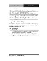
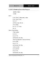
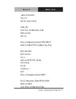
A.1 Programming
EMB-LN8T utilizes ITE 8712 chipset as its watchdog timer
controller.
Below are the procedures to complete its configuration and the
AAEON intial watchdog timer program is also attached based on
which you can develop customized program to fit your application.
Configuring Sequence Description
After the hardware reset or power-on reset, the ITE 8712 enters the
normal mode with all logical devices disabled except KBC. The
initial state (enable bit ) of this logical device (KBC) is determined
by the state of pin 121 (DTR1#) at the falling edge of the system
reset during power-on reset.
Summary of Contents for EMB-LN8T
Page 8: ...Mini ITX E M B L N 8 T Chapter 1 General Information 1 1 General Chapter 1 Information...
Page 16: ...Mini ITX E M B L N 8 T Chapter 2 Quick Installation Guide 2 4 Solder Side...
Page 18: ...Mini ITX E M B L N 8 T Chapter 2 Quick Installation Guide 2 6 Solder Side...
Page 32: ...Mini ITX E M B L N 8 T Chapter 3 AMI BIOS Setup 3 1 AMI Chapter 3 BIOS Setup...
Page 35: ...Mini ITX E M B L N 8 T Chapter 4 Driver Installation 4 1 Driver Chapter 4 Installation...
Page 49: ...Mini ITX E M B L N 8 T Appendix B I O Information B 1 I O Information Appendix B...
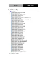
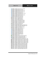
Page 50: ...Mini ITX E M B L N 8 T Appendix B I O Information B 2 B 1 I O Address Map...
Page 51: ...Mini ITX E M B L N 8 T Appendix B I O Information B 3...
Page 52: ...Mini ITX E M B L N 8 T Appendix B I O Information B 4 B 2 Memory Address Map...
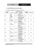
Page 54: ...Mini ITX E M B L N 8 T Appendix C Mating Connector C 1 Mating Appendix C Connector...