E m b e d d e d C o n t r o l l e r
A E C - 6 4 2 0
Chapter 2 Hardware Installation
2 - 8
Step 2: Pull out the rear panel from the chassis
Step 3: Insert the CompactFlash
Page 1: ...Embedded Controller A E C 6 4 2 0 AEC 6420 Compact Embedded Controller Intel Atom N270 1 6GHz Processor Dual LAN 4 USB 2 COM 1 PRT 1 VGA AEC 6420 Manual 2nd Ed August 2010 ...
Page 2: ...n this manual is intended to be accurate and reliable However the original manufacturer assumes no responsibility for its use or for any infringements upon the rights of third parties that may result from its use The material in this document is for product information only and is subject to change without notice While reasonable efforts have been made in the preparation of this document to assure...
Page 3: ...rd Software International Inc CompactFlash is a trademark of the Compact Flash Association Microsoft Windows is a registered trademark of Microsoft Corp Intel Atom are trademarks of Intel Corportation PC AT PS 2 and VGA are trademarks of International Business Machines Corporation All other product names or trademarks are properties of their respective owners ...
Page 4: ... make sure that the following materials are enclosed z 1 AEC 6420 Embedded Controller z 2 Wallmount Brackets z 1 Screw Package z 1 CD ROM for manual in PDF format and drivers If any of these items should be missing or damaged please contact your distributor or sales representative immediately ...
Page 5: ... DO NOT COVER THE OPENINGS 8 Make sure the voltage of the power source is correct before connecting the equipment to the power outlet 9 Position the power cord so that people cannot step on it Do not place anything over the power cord 10 All cautions and warnings on the equipment should be noted 11 If the equipment is not used for a long time disconnect it from the power source to avoid damage by ...
Page 6: ...QUIPMENT FCC This device complies with Part 15 FCC Rules Operation is subject to the following two conditions 1 this device may not cause harmful interference and 2 this device must accept any interference received including interference that may cause undesired operation Caution There is a danger of explosion if the battery is incorrectly replaced Replace only with the same or equivalent type rec...
Page 7: ...N Boxer Industrial System 有毒有害物质或元素 部件名称 铅 Pb 汞 Hg 镉 Cd 六价铬 Cr VI 多溴联苯 PBB 多溴二苯醚 PBDE 印刷电路板 及其电子组件 外部信号 连接器及线材 外壳 中央处理器 与内存 硬盘 电源 O 表示该有毒有害物质在该部件所有均质材料中的含量均在 SJ T 11363 2006 标准规定的限量要求以下 X 表示该有毒有害物质至少在该部件的某一均质材料中的含量超出 SJ T 11363 2006 标准规定的限量要求 备注 一 此产品所标示之环保使用期限 系指在一般正常使用状况下 二 上述部件物质中央处理器 内存 硬盘 电源为选购品 ...
Page 8: ...nd Jumpers of the Main Board 2 3 2 3 List of Jumpers 2 5 2 4 List of Connectors 2 6 2 5 Installing CompactFlash 2 7 2 6 Installing Hard Disk Drive 2 10 2 7 Wallmount Kit Installation 2 16 Chapter 3 Award BIOS Setup 3 1 System Test and Initialization 3 2 3 2 Award BIOS Setup 3 3 Chapter 4 Driver Installation 4 1 Installation 4 3 Appendix A Programming The Watchdog Timer A 1 Programming A 2 A 2 ITE8...
Page 9: ...Embedded Controller A E C 6 4 2 0 Chapter 1 General Information 1 1 General Chapter 1 Information ...
Page 10: ...he supermarket etc The advertising marketing industry will resort to every conceivable means to transmit product information to consumers System integrators will need a multifunction device to satisfy commercial needs for such public advertising Compact design for indoorEnvironment The AEC 6420 is designed for indoor environments due to the following reasons first the AEC 6420 offers low power con...
Page 11: ...traditional methods and become the mainstream controller for the multimedia entertainment market 1 2 Features z Intel AtomTM N270 1 6GHz Processor z DC 8 5 19 V Input with Lockable Connector and Optional External AC Input Power Adapter z Wallmount Design for Industrial Application z Windows XP Pro Windows XP Embedded and Linux Fedora Support ...
Page 12: ... port RS 232 x 1 COM1 RS 232 422 485 x 1 COM2 z USB USB 2 0 x 4 z Audio Line out x 1 Line in x 1 MIC x 1 z Printer port DB 25 printer port x 1 z Watchdog Timer Generates a time out system reset z Power Supply DC Input DC 8 5 19 V AC Input External power adapter Optional Note The power source of the Embedded Controller should be provided by a UL listed class 2 or Limited Power Source LPS with exter...
Page 13: ...x 2 6 H x 4 69 D 180 mm x 66 mm x 119 mm z Net weight 2 51 lb 1 14 kg z Gross weight 6 12 lb 2 78 kg z Operating Temperature 32 F 113 F 0 C 45 C z Operating Humidity 5 90 40 C non condensing z Vibration 0 5Grms 5 500Hz random operation CFD z Shock 20G peak acceleration 11msec duration CFD z EMC CE FCC Class A ...
Page 14: ...Embedded Controller A E C 6 4 2 0 Chapter 2 Hardware Installation 2 1 Hardware Installation Chapter 2 ...
Page 15: ...Embedded Controller A E C 6 4 2 0 Chapter 2 Hardware Installation 2 2 2 1 Dimension and I O of AEC 6420 ...
Page 16: ...Embedded Controller A E C 6 4 2 0 Chapter 2 Hardware Installation 2 3 2 2 Connectors and Jumpers of The Main Board Component Side ...
Page 17: ...Embedded Controller A E C 6 4 2 0 Solder Side Chapter 2 Hardware Installation 2 4 ...
Page 18: ...List of Jumpers The board has a number of jumpers that allow you to configure your system to suit your application The table below shows the function of each of the board s jumpers Jumpers Label Function JP1 VIO Voltage Selection JP3 Clear CMOS JP8 COM2 Ring 5V 12V Selection ...
Page 19: ...ction of each board s connectors Connectors Label Function CN5 Wide Voltage Power Connector CN7 18 bit LVDS Connector CN12 LPT port Connector CN14 Digital I O Connector CN22 CN23 GIGA Ethernet Connector CN24 COM1 COM2 Connector CN25 VGA Display Connector CN26 Compact Flash Disk Connector DIMM1 DDR II SODIMM Connector IDE1 Primary EIDE Connector SATA1 SATA2 SATA Connector USB1 USB1 USB2 Connectors ...
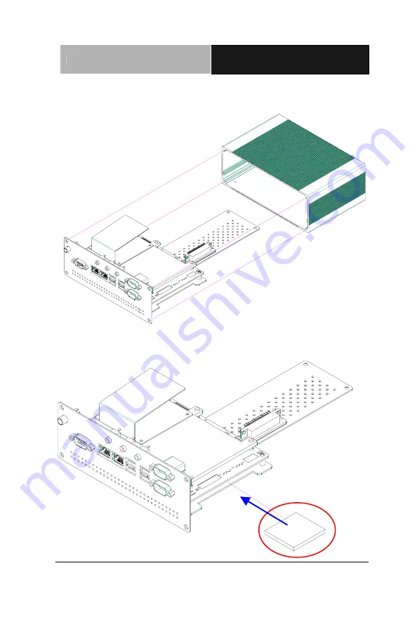
Page 20: ...Embedded Controller A E C 6 4 2 0 Chapter 2 Hardware Installation 2 7 2 5 Installing CompactFlash Step 1 Unfasten the eight screws on the front and rear panels ...
Page 21: ...Embedded Controller A E C 6 4 2 0 Chapter 2 Hardware Installation 2 8 Step 2 Pull out the rear panel from the chassis Step 3 Insert the CompactFlash ...
Page 22: ...Embedded Controller A E C 6 4 2 0 Chapter 2 Hardware Installation 2 9 Step 4 Fasten the eight screws of the front and rear panels and you have finished the CompactFlash installation ...
Page 23: ...ded Controller A E C 6 4 2 0 Chapter 2 Hardware Installation 2 10 2 6 Installing Hard Disk Drive Step 1 Stick the mylar on the Hard Disk Drive Step 2 Fasten the four screws to the bracket of Hard Disk Drive ...
Page 24: ...Embedded Controller A E C 6 4 2 0 Chapter 2 Hardware Installation 2 11 Step 3 Put the Dampers around the the four screws Damper Step 4 Put the dampers to the fillisters on the bracket ...
Page 25: ...Embedded Controller A E C 6 4 2 0 Chapter 2 Hardware Installation 2 12 Step 5 Use the four screws to fasten the bracket and the main board ...
Page 26: ...are Installation 2 13 Step 6 Insert the main board to the chassis Note When you install the main board kit to the chassis plea e watch out the IDE cable and prevent the IDE cable from damage Step 7 1 Install the SATA Hard Disk Drive s SATA Power Cable ...
Page 27: ...Embedded Controller A E C 6 4 2 0 Chapter 2 Hardware Installation 2 14 SATA Signal Cable Step 7 2 Install the IDE Hard Disk Drive ...
Page 28: ...Embedded Controller A E C 6 4 2 0 Chapter 2 Hardware Installation 2 15 Step 8 Fasten the eight screws on the front and rear panels to the chassis ...
Page 29: ... Hardware Installation 2 16 2 7 Wallmount Kit Installation Get the brackets ready and fasten appropriate four screws on each bracket After fastening the two brackets on the bottom lid of AEC 6420 the wallmount kit installation has been finished ...
Page 30: ...Embedded Controller A E C 6 4 2 0 Chapter 3 Award BIOS Setup 3 1 Chapter Award 3 BIOS Setup ...
Page 31: ...F1 key to continue the boot up sequence System configuration verification These routines check the current system configuration against the values stored in the CMOS memory If they do not match the program outputs an error message You will then need to run the BIOS setup program to set the configuration information in memory There are three situations in which you will need to change the CMOS sett...
Page 32: ...iately This will allow you to enter Setup Standard CMOS Features Use this menu for basic system configuration Date time IDE etc Advanced BIOS Features Use this menu to set the advanced features available on your system Advanced Chipset Features Use this menu to change the values in the chipset registers and optimize your system performance Integrated Peripherals Use this menu to specify your setti...
Page 33: ...menu to load the BIOS default values that are factory settings for optimal performance system operations While AWARD has designated the custom BIOS to maximize performance the factory has the right to change these defaults to meet their needs Set Password Use this menu to set Supervisor Password Save and Exit Setup Save CMOS value changes to CMOS and exit setup Exit Without Saving Abandon all CMOS...
Page 34: ...Embedded Controller A E C 6 4 2 0 Chapter 4 Driver Installation 4 1 Chapter Driver 4 Installation ...
Page 35: ... 2 0 1014 Driver Step 2 Install Intel Graphics Media Accelerator Driver Step 3 Install Intel Ethernet Driver Step 4 Install Realtek ALC655 Audio Driver v3 71 USB 2 0 Drivers are available for download using Windows Update for both Windows XP and Windows 2000 For additional information regarding USB 2 0 support in Windows XP and Windows 2000 please visit www microsoft com hwdev usb Please read inst...
Page 36: ...river 1 Click on the Step 2 Intel Graphics Media Accelerator Driver folder and select the OS folder your system is 2 Double click on the Setup exe in the OS folder 3 Follow the instructions that the window shows 4 The system will help you install the driver automatically Step 3 Install Intel Ethernet Driver 1 Click on the Step 3 Intel Ethernet Driver folder and select the OS folder your system is ...
Page 37: ...oller A E C 6 4 2 0 Chapter 4 Driver Installation 4 4 2 Double click on the setup exe file in the OS folder 3 Follow the instructions that the window shows 4 The system will help you install the driver automatically ...
Page 38: ...Embedded Controller A E C 6 4 2 0 Appendix A Programming the Watchdog Timer A 1 Programming the Appendix A Watchdog Timer ...
Page 39: ...itial watchdog timer program is also attached based on which you can develop customized program to fit your application Configuring Sequence Description After the hardware reset or power on reset the ITE 8781 enters the normal mode with all logical devices disabled except KBC The initial state enable bit of this logical device KBC is determined by the state of pin 121 DTR1 at the falling edge of t...
Page 40: ... Wait for Key state To ensure the initial state of the key check logic it is necessary to perform four write opera tions to the Special Address port 2EH Two different enter keys are provided to select configuration ports 2Eh 2Fh of the next step 2 Modify the Data of the Registers All configuration registers can be accessed after entering the MB PnP Mode Before accessing a selected register the con...
Page 41: ...mer Configuration Registers Configure Control Index 02h This register is write only Its values are not sticky that is to say a hardware reset will automatically clear the bits and does not require the software to clear them Watch Dog Timer 1 2 3 Control Register Index 71h 81h 91h Default 00h ...
Page 42: ...e Watchdog Timer A 5 Watch Dog Timer 1 2 3 Configuration Register Index 72h 82h 92h Default 001s0000b Watch Dog Timer 1 2 3 Time Out Value LSB Register Index 73h 83h 93h Default 38h Watch Dog Timer 1 2 3 Time Out Value MSB Register Index 74h 84h 94h Default 00h ...
Page 43: ...DEL SMALL CODE Main CALL Enter_Configuration_mode CALL Check_Chip mov cl 7 call Set_Logic_Device time setting mov cl 10 10 Sec dec al Watch_Dog_Setting Timer setting mov al cl mov cl 73h call Superio_Set_Reg Clear by keyboard or mouse interrupt mov al 0f0h mov cl 71h call Superio_Set_Reg unit is second mov al 0C0H mov cl 72h ...
Page 44: ...ov cl 9 call Set_Logic_Device Initial_OK CALL Exit_Configuration_mode MOV AH 4Ch INT 21h Enter_Configuration_Mode PROC NEAR MOV SI WORD PTR CS Offset Cfg_Port MOV DX 02Eh MOV CX 04h Init_1 MOV AL BYTE PTR CS SI OUT DX AL INC SI LOOP Init_1 RET Enter_Configuration_Mode ENDP Exit_Configuration_Mode PROC NEAR MOV AX 0202h ...
Page 45: ... RET Exit_Configuration_Mode ENDP Check_Chip PROC NEAR MOV AL 20h CALL Read_Configuration_Data CMP AL 87h JNE Not_Initial MOV AL 21h CALL Read_Configuration_Data CMP AL 81h JNE Not_Initial Need_Initial STC RET Not_Initial CLC RET Check_Chip ENDP Read_Configuration_Data PROC NEAR MOV DX WORD PTR CS Cfg_Port 04h ...
Page 46: ...iguration_Data ENDP Write_Configuration_Data PROC NEAR MOV DX WORD PTR CS Cfg_Port 04h OUT DX AL XCHG AL AH MOV DX WORD PTR CS Cfg_Port 06h OUT DX AL RET Write_Configuration_Data ENDP Superio_Set_Reg proc near push ax MOV DX WORD PTR CS Cfg_Port 04h mov al cl out dx al pop ax inc dx out dx al ret Superio_Set_Reg endp Set_Logic_Device proc near ...
Page 47: ...ar push ax push cx xchg al cl mov cl 07h call Superio_Set_Reg pop cx pop ax ret Set_Logic_Device endp Select 02Eh Index Port 02Fh Data Port Cfg_Port DB 087h 001h 055h 055h DW 02Eh 02Fh END Main Note Interrupt level mapping 0Fh Dh not valid 0Ch IRQ12 03h IRQ3 02h not valid 01h IRQ1 00h no interrupt selected ...