background image

2

MK20RC

English

RISQUE DE CHOC ELECTRIQUE 

NE PAS OUVRIR 

1.   Read  these  instructions  –  All  the  safety  and 

operating instructions should be read before this 

product is operated.

2.   Keep  these  instructions  –  The  safety  and 

operating  instructions  should  be  retained  for 

future reference.

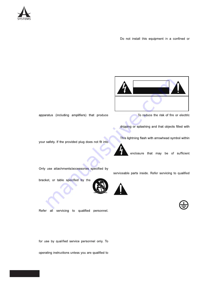
3.   Heed all warnings – All warnings on the appliance 

and  in  the  operating  instructions  should  be 

adhered to.

4.   Follow  all  instructions  –  All  operating  and  use 

instructions should be followed.

5.   Do  not  use  this  apparatus  near  water  –  The 

appliance  should  not  be  used  near  water  or 

moisture  –  for  example,  in  a  wet  basement  or 

near a swimming pool, and the like.

6.   Clean only with dry cloth.

7.   Do  not  block  any  ventilation  openings.  Install  in 

accordance with the manufacture’s instructions.

8.   Do  not  install  near  any  heat  sources  such 

as  radiators,  heat  registers,  stoves,  or  other 

heat.

9.   Do not defeat the safety purpose of the polarized 

or  grounding  plug.  A  polarized  plug  has  two 

blades with one wider than the other. A grounding 

plug has two blades and a third grounding prong. 

The wide blade or the third prong is provided for 

your outlet, consult an electrician for replacement 

of the obsolete outlet.

10.  Protect the power cord from being walked on or 

pinched  particularly  at  the  plugs,  convenience 

receptacles, and at the point where they exit from 

the apparatus.

11. 

the manufacturer.

12.  Use only with the cart, stand, tripod, 

manufacturer,  or  sold  with  the 

apparatus.  When  a  cart  or  rack  is 

used, use caution when moving the 

cart/apparatus combination to avoid 

injury from tip-over.

13.  Unplug the apparatus during lightning storms or 

when unused for long periods of time.

14. 

Servicing  is  required  when  the  apparatus  has 

been damaged in any way, such as power supply 

cord or plug is damaged, liquid has been spilled 

or objects have fallen into the apparatus has been 

exposed  to  rain  or  moisture,  does  not  operate 

normally, or has been dropped.

15.  CAUTION:  These  servicing  instructions  are 

reduce the risk of electric shock, do not perform 

any  servicing  other  than  that  contained  in  the 

do so.

16. 

building-in space such as a book case or similar 

unit,  and  remain  a  well  ventilation  conditions  at 

open site. The ventilation should not be impeded 

by  covering  the  ventilation  openings  with  items 

such as newspaper, table-cloths, curtains, etc.

17. 

WARNING: 

The mains plug/appliance coupler is 

used as disconnect device, the disconnect device 

shall remain readily operable.

18.  This apparatus is for professional use only.

19. 

WARNING:

shock,  do  not  expose  this  apparatus  to  rain  or 

moisture. The apparatus shall not be exposed to 

liquids,  such  as  vases,  shall  not  be  placed  on 

apparatus.

20.  

an equilateral triangle is intended to alert 

the user to the presence of non-insulated 

“dangerous  voltage”  within  the  product’s 

magnitude  to  constitute  a  risk  of  electric 

shock.

Warning:

  To  reduce  the  risk  of  electric  shock,  do 

not  remove  cover  (or  back)  as  there  are  no  user-

personnel.
 

The exclamation point within an equilateral 

triangle  is  intended  to  alert  the  user  to 

the  presence  of  important  operating  and 

maintenance  instructions  in  the  literature 

accompanying the appliance.

21.  Protective  earthing  terminals.  The 

apparatus  should  be  connected  to  a 

mains  socket  outlet  with  a  protective 

earthing connection.

RISQUE DE CHOC ELECTRIQUE

NE PAS OUVRIR

ATTENTION

AVERTISSEMENT: POUR REDUIRE LE RISQUE DE CHOC


ELECTRIQUE, NE RETIREZ P AS LE COUVERCLE (OU L'ARRIERE), 

PAS DE PIECE RE PARABLE PAR L'UTILISATEUR A L'INTERIEUR


CONFIEZ LES RE PARATIONS A UN PERSONNEL QUALIFIE .

IMPORTANT SAFETY INSTRUCTIONS

Summary of Contents for MK20RC

Page 1: ...User s Manual Pan Tilt Zoom Camera Remote Control MK20RC...

Page 2: ...n the apparatus has been damaged in any way such as power supply cord or plug is damaged liquid has been spilled or objects have fallen into the apparatus has been exposed to rain or moisture does not...

Page 3: ...Lever Calibration 13 Basic Menu Operations 14 Preset Saving Deleting Operations 15 Hot Key Presets 16 Menu Options 17 LCD Menu Options 20 I Camera Setup 20 II Exposure 21 III Focus 22 IV White Balanc...

Page 4: ...C it is highly recommended that you carefully read through Safety Instructions section first for safe operation while avoiding hazardous situations OVERVIEW MK20HD is a compact PTZ camera remote contr...

Page 5: ...tilt zoom focus and iris operations of the cameras can be easily performed from the unit while the gain shutter detail and white balance adjustments can be performed on the unit s LCD menu 40 preset m...

Page 6: ...please carefully inspect the included items in the unlikely event of any missing or damaged items please contact your authorized retailer distributor for replacements MK20HD MK20RC Owner s Manual Pow...

Page 7: ...Camera 5 SDI SDI SDI SD INI SD INI SD INI SD INI TALLY IN CAMERA CONTROL VIDEO OUTPUTS MK20RC TALLY OUT RS485 RS485 RS485 RJ45 T Splitter RS485 RS485 RS485 CAT 5 HDMI DVI CAT 5 HDMI DVI IN VIDEO SWIT...

Page 8: ...OUTPUTS CAMERA CONTROL MK20RC TALLY OUT RS422 1 RS422 1 RS422 2 RS422 2 RS422 3 RS422 3 RS422 4 RS422 4 RS422 5 RS422 5 CAT 5 HDMI DVI CAT 5 HDMI DVI IN VIDEO SWITCHER AV800HD Point to Point Control C...

Page 9: ...ufficiently strong stable and level surface for use Ensure a space of at least 100 mm 3 15 16 around the front vents to avoid obstructing ventilation In particular ensure sufficient space between vent...

Page 10: ...id using the product at a humid dusty place humidity and dust will cause damage to the parts inside the unit Maintenance Wipe the product using a dry cloth to remove stubborn dirt dip a cloth into a d...

Page 11: ...ne mode selection menu 5 Shutter Controls Knob Select manual shutter speed Auto Button Enable auto shutter feature Disable manual shutter 6 Iris Controls Knob Select manual iris opening Auto Button En...

Page 12: ...focus rotary knob and one touch focus will be disabled 12 Mute Mutes and turns the screen black 13 CTRL ENA Control Enable Enable to unlock all top panel controls 14 Preset and Hot Key Buttons 1 10 15...

Page 13: ...ion Port Camera 1 to 5 control communication in Daisy Chain mode 3 RS422 Control Communication Ports 1 to 5 Camera 1 to 5 communication in point to point mode 4 Power Switch 5 Communication Port Selec...

Page 14: ...eds 5 Adjust the zoom Use the ZOOM control lever to adjust the lens zoom When the lever is pushed towards UP the zoom is set to the telephoto mode when the lever is pushed towards DOWN th e zoom is se...

Page 15: ...the LCD command prompt Follow the steps on the LCD screen to recalibrate the Joystick First by rotating the Joystick around to all four corners press ENTER when finished Then put the Joystick to its...

Page 16: ...select the menus and change the settings Use the F1 dial for operations involving the items displayed on the top column of the LCD panel Use the F2 dial for operations involving the items displayed on...

Page 17: ...t the custom setting shutter speed iris exposure setting white balance etc 3 Press SAVE button to save A confirmation prompt will show up on the LCD screen use F2 to select saving or canceling then pr...

Page 18: ...exposure settings in environments with great lighting contrasts The Hot Key Presets will store the following values Gain 3 to 18 dB Default 0 Iris Close to Open Shutter 1 30 to 1 10000 Once the gain i...

Page 19: ...IONS Main Menu Camera Setup COM Setup Baud Rate Data Bit Parity Stop Bit Flow Control Invert Tilt Tally Setup CAM 1 5 Exposure Mode Auto Manual Priority Brightness Gain Speed Iris EX Comp Level Spot A...

Page 20: ...up Normal Interval Zoom Trig Act Time Int Time Auto Scene White Balance One Push Manual Red Gain Blue Gain Pan Limit Pan Setup Pan Tilt Zoom Right Limit B Zone C Zone D Zone Tilt Limit Tilt Setup Up L...

Page 21: ...MK20RC English Zoom Setup B Zone C Zone D Zone Hi Zoom Speed Lo Zoom Speed Dead Zone Picture Aperture System OSD Image Info Display Factory Reset Camera Select Controller ID Ca Zoom lever Power Contr...

Page 22: ...a guideline when adjusting MK20RC s settings for optimal video results I Camera Setup Underlined values are set as system default values Level 1 F1 Level 2 F2 Level 3 F2 Level 4 F2 Camera Setup COM S...

Page 23: ...4 F2 Exposure Mode Auto Auto Manual Select Manual Exposure to enable Priority Priority Iris Brightness Brightness 0 23 Gain 3 28 dB DF 0 Speed 1 30 1 10000 Iris Close to F1 6 Exposure Ex Comp On 10 5...

Page 24: ...I Focus Underlined values are set as system default values Level 1 F1 Level 2 F2 Level 3 F2 Level 4 F2 Focus Auto On Exposure Auto Setup AF Normal On AF Interval On AF Zoom Trig On AF Act Time 000 255...

Page 25: ...ideline when adjusting MK20RC s settings for optimal video results Level 1 F1 Level 2 F2 Level 3 F2 Level 4 F2 White Balance Auto White Balance On When a Scene has been selected Auto White Balance Whi...

Page 26: ...etup L 179 179 Default at 0 Right Pan Limit 179 179 Default at 0 B Zone Pan Speed 0 23 Default at 2 C Zone Pan Speed 0 23 Default at 12 D Zone Pan Speed 0 23 Default at 22 Tilt Limit Tilt Limit On Til...

Page 27: ...0 24 Default at 12 D Zone Tilt Speed 0 24 Default at 22 Zoom Setup Zoom Setup B Zone Range 0 7 C Zone R ange 0 7 Default at 3 D Zone Range 0 7 Hi R ange 0 7 Default at 6 Lo Range 0 7 Default at 1 Dea...

Page 28: ...he screen display of the camera on and off Level 1 F1 Level 2 F2 Level 3 F3 Picture Black White Aperture Min 01 14 Max Level 1 F1 Level 2 F2 Level 3 F3 Level 4 F4 System OSD On System Normal Horizonta...

Page 29: ...deployed System Controller ID 1 8 Torecalibrate System Torecalibrate the Zoom Lever of the console System System Choose to turn on PTZ cameras individually or altogether Power Control All One Note Po...

Page 30: ...ed zoom Lo Fixed low speed zoom 4 Camera Support 5 5 Preset Memory 40 6 Tally Light DA15 x2 PGM PVW 7 Communication RJ 45 RS422 x5 RJ 45 RS485 x1 up to 1000m Daisy Chain 5 cameras 8 Top Panel Function...

Page 31: ...F 0 e Speed Same status as top panel 1 30 to 1 10000 f Iris Same status as top panel Close to Open g Exp Comp OFF 10 5 to 10 5 h Spot AE OFF ON i Spot AE H Pos 00 to 15 j Spot AE V Pos 00 to 15 3 Focu...

Page 32: ...one Speed DF 2 0 to 23 k Tilt C Zone Speed DF 12 0 to 23 l Tilt D Zone Speed DF 22 0 to 23 m Zoom B Zone Speed 0 to 7 n Zoom C Zone Speed DF 3 0 to 7 o Zoom D Zone Speed 0 to 7 p Hi Zoom Speed DF 6 0...

Page 33: ...Menu Status AUTO Manual 5 Iris a Auto OFF ON b Iris Position Same as Setup Menu Status save last adjusted data Close to Open 6 Shutter a Auto OFF ON b Shutter Position Same as Setup Menu Status save...

Page 34: ......

Page 35: ......

Page 36: ...www asystems sys com...

Reviews: