A.O. Smith VF VB 1000 User Manual Download Page 14

14

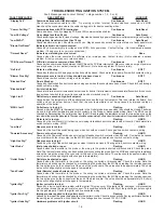
blower prover does not activate after 15 seconds. This time 

allows the blower relay to activate, the blower to come up to 

speed, and the response from the blower prover to be filtered.

•  User Settings Screen:

  Each setpoint or user setting has either a limited selection of 

values, or a limited range of values.  The Up/Down keys are 

used to change values.  After changing an item, the Select key 

is pressed to accept the change, or the Menu key is pressed 

to reject the change and restore the item to its original value.  

The following setpoints can be changed:


•  Operating Setpoint:

  This setpoint sets the base temperature for the control algorithm.

OPERATING SETPOINT ADJUSTMENT PROCEDURE

The system has a standard programmable operating Setpoint 

range of 70°F (21°C) to 190°F (88°C) for a vW and of 70°F 

(21°C) to 220°F (104°C) for a vB for either a Remote or inlet 

probe depending on selection. The user can easily change 

the operating Setpoint at any time by using the following 

procedure. When any configuration or setpoint is changed 

(and the Select key touched), the new value is IMMEDIATElY 

saved to non-volatile memory. The factory default setting is 

145°F (49°C).

1.  Press the MENU key.

2.  Scroll the “>” with the DoWN key next to the USER SETTING 

SCREEN.

3.  Press the SElECT key.

4.  Scroll the “>” with the DoWN key until it is pointing to 

oPERATING SETPoINT.

5.  Press the SElECT key.

6.  Use the UP or DoWN key to select the value you wish to enter.

7.  Press the SElECT key to accept and store the new value.

•  High Limit:

  The outlet temperature probe contains both an ECo switch 

and a thermistor for temperature measurement. The sensed 

outlet temperature is used for the automatically resettable High 

limit setpoint. If the sensed outlet temperature exceeds the 

High limit setpoint, a “soft lockout” condition will occur and 

the burner will be shut off. This fault condition is automatically 

cleared when the temperature drops below the high limit 

setpoint minus the high limit differential.

AUTO HIGH LIMIT SETPOINT ADJUSTMENT PROCEDURE/

OUTLET TEMPERATURE PROBE

The High limit setpoint has a range of 90°F (32°C) to 210°F  (99°C) 

for a vW and a range of 90°F (32°C) to 235°F (113°C) for a vB.  

Use the following procedure to change the automatically resettable 

High limit Setpoint:

1.  Press the MENU key.

2.  Scroll the “>” with the DoWN key next to USER SETTING SCREEN.

3.  Press the SElECT key.

4.  Scroll the “>” with the DoWN key until it is pointing to HIGH 

lIMIT SETPoINT.

5.  Press the SElECT KEY.

6.  Use the UP and DoWN key to select the value you wish to enter.

7.  Press the SElECT key to accept and store the new value.

•  High Limit Differential:

  The outlet temperature must be below the automatic High limit 

setpoint minus the High limit Differential setpoint before  a call 

for heat can be generated.

HIGH LIMIT DIFFERENTIAL SETPOINT ADJUSTMENT 

PROCEDURE

The High limit Differential Setpoint has a range of 1°F to 50°F for 

all models. Use the following procedure to change the High limit 

Differential Setpoint:
1.  Press the MENU key.
2.  Scroll the “>” with the down key next to USER SETTING 

SCREEN.

3.  Press the SElECT key.
4.  Scroll the “>” with the DoWN key until it is pointing to HIGH 

lIMIT DIFFERENTIAl SETPoINT.

5.  Press the SElECT key.
6.  Use the UP or DoWN key to select the value you wish to enter.
7.  Press the SElECT key to accept and store the new value.

•  Operating  Differential  Setpoints:

  Each of the two stages has an independent operating 

Differential setpoint.

• 

Temperature Units:

  Temperature can be displayed in either °F or °C units.

• 

Post Circulate Delay Time:

  The time circulation pump will stay on after the burner 

is turned off. The time in seconds is adjustable with 

the following values: 45, 90, 180 or continuous.  If the 

continuous value is selected the pump will remain on at 

all times and the post circulate state time will be set at 

45 seconds.

• 

Network Address:

  This is a unique number assigned to this boiler to differentiate 

it from other boilers or water heater on the same A. o. 

Smith proprietary network. A valid Network Address can be 

any number from 0 to 31. It is set by default to zero, which 

is an invalid address. The boiler will not communicate until 

it is changed to a valid and unique number. This prevents 

two units from trying to respond to the same request from 

the PC or supervisory network device.

• 

Configuration Settings Screen:

  Displays the status of the dipswitches installed on all 

boards as described earlier.

• 

Log & System Info Screen:

  Displays the following information:
  Elapsed hours of operation (Total time system has been 

powered up)

  Number of running minutes (Number of minutes system has 

been in the run mode)

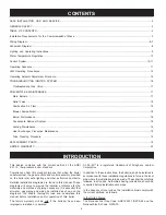
Summary of Contents for VF VB 1000

Page 1: ...se any phone in your building Immediately call your gas supplier from a neighbor s phone Follow the gas supplier s instructions If you cannot reach your gas supplier call the fire department Installation and service must be performed by a qualified installer service agency or the gas supplier PRINTED 0411 320857 000 USER S MANUAL MODELS VB VW 500 750 AND 1000 SERIES 200 201 GAS FIRED POWER BURNER ...

Page 2: ...ances known to the State of California to cause cancer birth defects or other reproductive harm and requires businesses to warn of potential exposure to such substances This product contains a chemical known to the State of California to cause cancer birth defects or other reproductive harm This appliance can cause low level exposure to some of the substances listed in the Act IMPORTANT DEFINITION...

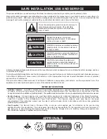
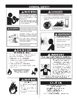
Page 3: ...3 GENERAL SAFETY ...

Page 4: ...ntrol assembly pro vided on the boiler met safe lighting and other performance criteria Detailed installation diagrams are found in this manual These diagrams will serve to provide the installer a reference for the materials and methods of piping necessary It is essential that all water gas piping and wiring be installed as shown on the diagrams You should thoroughly read and understand this manua...

Page 5: ...ntally vented gas fueled heating appliance or equipment The sign shall read in print size no less than one half 1 2 inch in size GAS VENT DIRECTLY BELOW KEEP CLEAR OF ALL OBSTRUCTIONS INSPECTION The state or local gas inspector of the side wall horizontally vented gas fueled equipment shall not approve the installation unless upon inspection the inspector observes carbon monoxide detectors and sig...

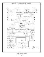
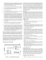
Page 6: ...6 CONNECTION DIAGRAM ...

Page 7: ...7 ...

Page 8: ...8 Figure 1 SCHEMATIC DIAGRAM VB VW 500 750 1000 SCHEMATIC DIAGRAM ...

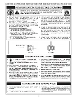
Page 9: ...9 LIGHTING OPERATION INSTRUCTIONS FOR MODELS VB VW 500 750 AND 1000 ...

Page 10: ...ystem or something similar Through this connection multiple boilers can also be linked together CAUTION The internal communications cables should never be connected to the external communications connectors and vice versa There are several microcontrollers used on the boards These control the temperature and ignition control functions for the boiler Inherent in the design are the normal operating ...

Page 11: ...ame rod is missing or shorted the flame will not be detected OUTPUTS FROM MCB Relay Contact Output Alarm MCB 24VAC optional Provides electrical power to operate an external alarm This can be an audio device i e Sonalert a visual device lamp or any other device that will operate with the voltage and current level provided Pump MCB 120VAC required on systems that do not have an external pump Provide...

Page 12: ...nu activated screens Within each of the screens helpful information can be displayed by pressing the Help button The LED s visually inform the user about the mode the system is in The touch switches allow the user to control the operation of the system The operation of these parts is described in the following section UIM Screens On all screens a double vertical bar appears on the right side of th...

Page 13: ...a jump to the error state Description of FCB control states Idle State When any error is declared during idle state The system will remain in this state until the MCB request a heating cycle or a cold purge Pre Purge State The blower is turned on After 10 to 34 seconds 34 seconds for cold purging the system switches to the Heat Igniter State Heat Igniter State The sequence of operation is as follo...

Page 14: ... to change the automatically resettable High Limit Setpoint 1 Press the MENU key 2 Scrollthe withtheDOWNkeynexttoUSERSETTINGSCREEN 3 Press the SELECT key 4 Scroll the with the DOWN key until it is pointing to HIGH LIMIT SETPOINT 5 Press the SELECT KEY 6 Use the UP and DOWN key to select the value you wish to enter 7 Press the SELECT key to accept and store the new value High Limit Differential The...

Page 15: ...ards in screens to reach a desired item and to change setpoints and user settings They have an auto increment decrement feature for some of the configurations and values When you first press one of the keys and value changes by 1 count then wait 1 2 second and changes slowly until the key is released or if held for 3 or more seconds it will change the value quickly Help Key Pressing the Help key f...

Page 16: ...nected wiring Note The MRHL can be checked by disconnecting the outlet probe from the MCB and reading the resistance across the two active pins on the connectorattheendoftheprobecable Thevalueshouldbeapproximately0ohmswhenthetemperatureoftheprobeislessthan220 F Low Water Water level is too low Flashing HARD Caused by the Low Water Cut Out device not closing its feedback switch contacts when it sho...

Page 17: ...r Give reasonably quiet operation during initial ignition operation and extinction Cause no excessive lifting of flame from burner ports If the preceding burner characteristics are not evident check for accumulation of lint or other foreign material that restricts or blocks the air openings to the burner or boiler To check burners 1 Shut off all gas and electricity to unit Allow unit to cool 2 Rem...

Page 18: ...sible shortened service life BURNER MAINTENANCE Qualified servicers should follow this procedure when the boiler s burner needs cleaning 1 Turn off the electrical power to the boiler and close the main manual gas shutoff valve s Allow the boiler parts to cool before disassembly 2 Loosen the flange and separate the gas train from the manifold assembly 3 Separate the burner from the blower adapter b...

Page 19: ...ssolidsexist Asthewaterisheated these tendtodropoutdepositingasscaleorlime Thisscalemustberemoved before the heat exchanger tubes become blocked DELIMING The amount of calcium carbonate lime released from water is in direct proportion to water temperature and usage The higher the water temperature or water usage the more lime deposits are dropped out of the water This is the lime scale which forms...

Page 20: ...20 notes ...

Page 21: ...21 notes ...

Page 22: ...22 notes ...

Page 23: ...ration for the boiler or any of its parts Some states and provinces do not allow limitations on how long an implied warranty lasts so the above limitation may not apply to you 5 CLAIM PROCEDURE Any claim under this warranty should be initiated with the dealer who sold the boiler or with any other dealer handling the warrantor s products If this is not practicable the owner should contact U S Custo...

Page 24: ...24 500 Tennessee Waltz Parkway Ashland City TN 37015 Technical Support 800 527 1953 Parts 800 433 2545 Fax 800 644 9306 www hotwater com ...

Reviews: