


25
8
Start-up
Introduction
This section provides the pre-optional checks, initial start-up
and operating procedures for the APW water heater.
Pre-operational checks and procedures
All APW installation procedures provided in Section 2
- Prepare Water Heater must be fully completed prior
to performing Pre-Operational checks. In addition, the
following items should be checked:
1. Ensure that external single-phase AC power at 120
VAC/60 Hz is properly connected to the electronic
control system control box.
2. Open the isolation valve in the cold water inlet line to the
APW water heater.
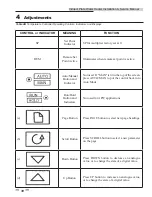
3. Verify that the electronic control system temperature
controller set point and over-temperature switch alarm
limit have been properly set using the procedures in
Section 4 - Adjustments.
4. The air vent, located in the top of the manifold, allows
air to escape during the fill process (a hissing sound may
be heard). If a hissing sound is not heard through the air
vent, close the air vent cap and then open it two (2) full
turns counterclockwise. DO NOT remove the air vent
cap.
5. When hissing sound from the air vent stops, carefully
open the pressure and temperature (P & T) relief valve to
vent any remaining air.
6. Close the P & T relief valve when the heater is full.
DO NOT operate equipment exceeding
design conditions as specified on the
nameplate.
The APW must never be subjected to
pressure greater than the maximum
differential pressure specified on the
nameplate.
Sudden rises in pressure may cause leakage
or damage to plates or gaskets of double-
wall models.
Fluids MUST BE gradually introduced
to the unit. Failure to do so can cause
damage to heat exchanger plates. When
the unit is empty or cold, DO NOT admit
hot fluid to the unit suddenly. When unit
is hot, DO NOT shock with cold fluid.
⚠
WARNING
⚠
CAUTION
Initial start-up
In order to prevent a possible over-temperature condition
during initial start-up, The manufacturer recommends that the
following steps be performed in the order specified:
1. Set the POWER switch on the front of the box to the
ON position. This will provide power to the complete
electronic control system and control valve. When power is
initially applied, the electronic control system temperature
controller automatically performs a self-test sequence for
approximately three (3) seconds. Proceed immediately to
the next step.
2. Upon completion of the self-test, the temperature controller
will show the present water heater outlet temperature
in the upper display and the set point temperature is
displayed right below that.
3. Open the stop valve in the building recirculation system, if
employed.
4. Open the isolation valve in the hot water outlet line.
Connect a hose to the field-piped hose connection (see
piping diagrams in Section 3- Hydronic Piping or open
several hot water fixtures in the building to ensure water
flow through the heater.
5. Slowly open the isolation valves in the water inlet and
water outlet connections of the heater.
6. When in the AUTO Mode, the electronic control system
will stabilize at the selected set point temperature. Once
stabilized, the electronic control system is set for unattended
operation with no further operator intervention. The
control may take several minutes to stabilize. Temperature
may vary during this time. Stabilized when bottom PV is
near bottom SP (0).
7. Close the hose connection or hot water fixtures opened in
Step 4.
8. During start-up of double-wall models, there may be some
evidence of leakage prior to the plates and gaskets reaching
their working temperature. If leakage continues, contact
the factory for assistance.
Indirect Plate Water Heater Installation & Service Manual