


71
Servicing should only be performed by a Qualified Service Agent
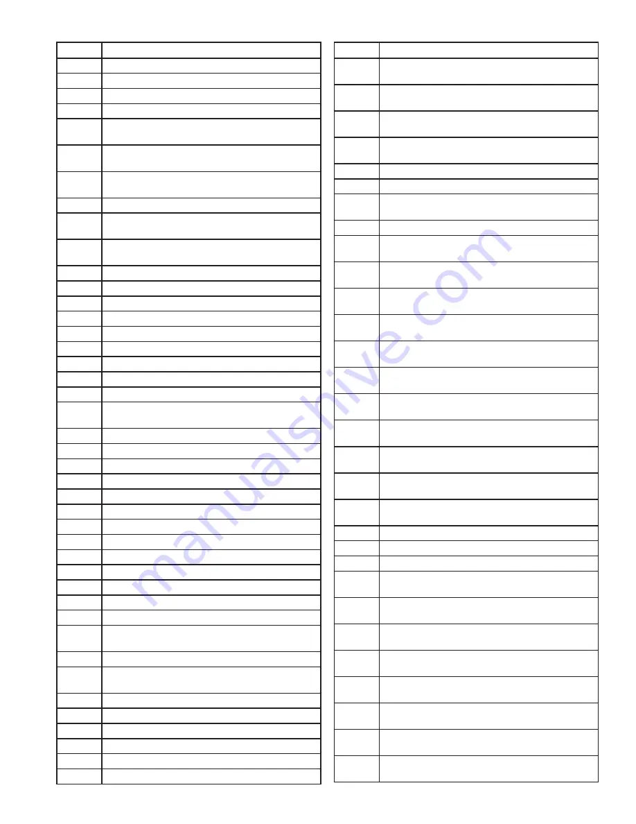
CODE
DESCRIPTION
231
Lead Lag CH setpoint was invalid
232
Lead Lag CH time of day setpoint was invalid
233
LL outdoor temperature was invalid
234
Lead Lag ODR time of day setpoint was invalid
235
Lead Lag ODR time of day setpoint exceeded
normal setpoint
236
Lead Lag ODR max outdoor temperature was
invalid
237
Lead Lag ODR min outdoor temperature was
invalid
238
Lead Lag ODR low water temperature was invalid
239
Lead Lag ODR outdoor temperature range was
too small (minimum 12°C/22°F)
240
Lead Lag ODR water temperature range was too
too small (minimum 12°C/22°F)
241
Lead Lag DHW setpoint was invalid
242
Lead Lag Mix setpoint was invalid
243
Lead Lag CH demand switch was invalid
244
Lead Lag CH setpoint source was invalid
245
RESERVED
246
CH setpoint was invalid
247
CH time of day setpoint was invalid
248
CH outdoor temperature was invalid
249
CH ODR time of day setpoint was invalid
250
CH ODR time of day setpoint exceeds normal
setpoint
251
CH max outdoor setpoint was invalid
252
CH min outdoor setpoint was invalid
253
CH min water setpoint was invalid
254
CH outdoor temperature range was too small
255
CH water temperature range was too small
256
Steam setpoint was invalid
257
Steam time of day setpoint was invalid
258
Steam minimum pressure was invalid
259
CH ODR min water temperature was invalid
260
RESERVED
261
DHW setpoint was invalid
262
DHW time of day setpoint was invalid
263
DHW storage setpoint was invalid
264
STAT may not be a DHW demand source when
Remote Stat is enabled
265-266 RESERVED
267
STAT may not be a CH demand source when
Remote Stat is enabled
268
CH 4mA water temperature setting was invalid
269
CH 20mA water temperature setting was invalid
270
Steam 4mA water temperature setting was invalid
271
Steam 20mA water temperature setting was invalid
272
Abnormal Recycle: Pressure sensor fault
273
Abnormal Recycle: Safety relay drive test failed
CODE
DESCRIPTION
274
Abnormal Recycle: Demand off during Pilot Flame
Establishing Period
275
Abnormal Recycle: LCI off during Drive to Purge
Rate
276
Abnormal Recycle: LCI off during Measured Purge
Time
277
Abnormal Recycle: LCI off during Drive to Lightoff
Rate
278
Abnormal Recycle: LCI off during Pre-Ignition test
279
Abnormal Recycle: LCI off during Pre-Ignition time
280
Abnormal Recycle: LCI off during Main Flame
Establishing Period
281
Abnormal Recycle: LCI off during Ignition period
282
Abnormal Recycle: Demand off during Drive to
Purge Rate
283
Abnormal Recycle: Demand off during Measured
Purge Time
284
Abnormal Recycle: Demand off during Drive to
Lightoff Rate
285
Abnormal Recycle: Demand off during Pre-Ignition
test
286
Abnormal Recycle: Demand off during Pre-Ignition
time
287
Abnormal Recycle: Flame was on during Safe
Check
288
Abnormal Recycle: Flame was on during Drive to
Purge Rate
289
Abnormal Recycle: Flame was on during
Measured Purge Time
290
Abnormal Recycle: Flame was on during Drive to
Lightoff Rate
291
Abnormal Recycle: Flame was not on at end of
Ignition period
292
Abnormal Recycle: Flame was lost during Main
Flame Establishing Period
293
Abnormal Recycle: Flame was lost early in Run
294
Abnormal Recycle: Flame was lost during Run
295
Abnormal Recycle: Leakage test failed
296
Abnormal Recycle: Interrupted air flow switch was
off during Drive to Purge Rate
297
Abnormal Recycle: Interrupted air flow switch was
off during Measured Purge Time
298
Abnormal Recycle: Interrupted air flow switch was
off during Drive to Lightoff Rate
299
Abnormal Recycle: Interrupted air flow switch was
off during Pre-Ignition test
300
Abnormal Recycle: Interrupted air flow switch was
off during Pre-Ignition time
301
Abnormal Recycle: Interrupted air flow switch was
off during Main Flame Establishing Period
302
Abnormal Recycle: Ignition failed due to
interrupted air flow switch was off
303
Abnormal Recycle: ILK off during Drive to Purge
Rate
Summary of Contents for 100 Series
Page 2: ...2 Servicing should only be performed by a Qualified Service Agent...
Page 77: ...77 Servicing should only be performed by a Qualified Service Agent NOTES...
Page 78: ...78 Servicing should only be performed by a Qualified Service Agent NOTES...
Page 79: ...79 Servicing should only be performed by a Qualified Service Agent NOTES...


