background image

A.H. Systems SAS-547 Biconical Antenna

 A.H. Systems inc. – Nov 2014

REV B

12

Summary of Contents for SAS-547

Page 1: ...A H Systems SAS 547 Biconical Antenna SAS 547 Biconical Antenna Operation Manual A H Systems inc Nov 2014 REV B 1 ...

Page 2: ...ional Equipment 4 Intended Purposes 5 OPERATING INSTRUCTIONS Assembly Instructions 6 Mounting Instructions 6 SPECIFICATIONS Specifications 9 Typical Data 10 Calculations 14 Convertion Formulas 15 MAINTENANCE Maintenance Procedures 16 Annual Calibration 16 A H Systems inc Nov 2014 REV B 2 ...

Page 3: ...ON The A H Systems SAS 547 Biconical antenna operates efficiently over the frequency range of 1 GHz to 18 GHz Compact in size this Biconical Antenna is an ideal solution for broadband and Omni directional requirements A H Systems inc Nov 2014 REV B 3 ...

Page 4: ...dapter We stock those as well MOUNTING ACCESSORIES AEH 510 Azimuth and elevation head to assist the test engineer in orientating biconical antenna at the device under test ATU 510 Each tripod leg is independently adjustable in angle and length to facilitate antenna height setting The tripod legs have a rubber tip on one end for indoor or hard surface use and a metal spike on the other end for outd...

Page 5: ...igned to be used in the process of generating controlling and measuring high levels of electromagnetic Radio Frequency RF energy It is the responsibility of the user to assure that the device is operated in a location which will control the radiated energy such that it will not cause injury and will not violate regulatory levels of electromagnetic interference A H Systems inc Nov 2014 REV B 5 ...

Page 6: ...g clamp azimuth and elevation head AEH 510 through the screw hole in the antenna base The azimuth and elevation head AEH 510 mounts to the tripod ATU 510 top and allows the antennas to be rotated 360 degrees and tilted between horizontal and vertical polarization Each tripod leg is independently adjustable in angle and length to facilitate antenna height setting The tripod legs have a rubber tip o...

Page 7: ...e antenna as pictured in illustration 1 for vertical omnidirectional testing Rotating the antenna 90 degrees so that the antenna is parallel to the ground for horizontal testing The horizontal beamwidth of the biconical antenna is approximately 60 degrees and the nameplate should be pointed or aimed in the direction that the received signal is coming from A H Systems inc Nov 2014 REV B 7 Illustrat...

Page 8: ...rors it is recommended that high quality in line attenuators be used to reduce reflections Connect the attenuator at the antenna end of the transmitting cable or when receiving connect the attenuator at the measuring instrument or preamplifier input Dress the cables straight back from the antenna connector at least 1 meter before being dressed vertically down to the ground plane Signal cables that...

Page 9: ...Hz 18 GHz Antenna Factor 30 to 60 dB m Antenna Gain 10 to 4 dBi Impedance nominal 50W Average VSWR 2 0 1 typ Maximum Continuous Power 50 Watts Connector N Type female Mounting 1 4 20 female PHYSICAL SPECIFICATIONS Weight 1 lbs 454 g Size W x H 2 25 x 14 25 6cm x 36cm A H Systems inc Nov 2014 REV B 9 ...

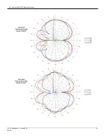
Page 10: ...A H Systems SAS 547 Biconical Antenna TYPICAL DATA A H Systems inc Nov 2014 REV B 10 ...

Page 11: ...A H Systems SAS 547 Biconical Antenna A H Systems inc Nov 2014 REV B 11 ...

Page 12: ...A H Systems SAS 547 Biconical Antenna A H Systems inc Nov 2014 REV B 12 ...

Page 13: ...A H Systems SAS 547 Biconical Antenna A H Systems inc Nov 2014 REV B 13 ...

Page 14: ...factor plus cable loss to receiver reading in dB V to convert to field strength in dB V meter Field Strength dBuV m SA dBuV AF dB m cable loss dB SA Spectrum Analyzer or Receiver voltage reading AF Antenna Correction Factor CL Cable Loss in dB IMMUNITY TESTING For Immunity measurements the generated electric field strength can be calculated by FS Approximate Field Strength in V m P Power in watts ...

Page 15: ...T T 1 25 A m dB A to dBA dBA dB A 120 E FIELD ANTENNAS LOG LINEAR POWER Correction Factor dB V m dB V AF dBm to Watts W 10 dBm 30 10 Field Strength V m 30 watts Gain numeric meters Watts to dBm dBm 10log W 30 Required Power Watts V m meters 2 30 Gain numeric dBW to Watts W 10 dBW 10 LOOP ANTENNAS Watts to dBW dBW 10log W Correction Factors dB A m dB V AF dBW to dBm dBm dBW 30 Assumed E field for s...

Page 16: ...ssions testing for electromagnetic compatibility EMC requires the measurement of electric field E field strength which is compared with a limit level The output voltage of an antenna is converted to E field strength via its antenna factor the measurement of which must include the uncertainty components related to that particular antenna taking into consideration the environment in which the antenn...

Page 17: ... with the delivery of the product by A H Systems The remedy set forth herein shall be the only remedy available to the buyer and in no event shall A H Systems be liable for direct indirect incidental or consequential damages This warranty shall not apply to any part of the product which without fault of A H Systems has been subject to alteration failure caused by a part not supplied by A H Systems...

Reviews: