Page 14
VTX series instructions
wrong voltage, will normally still go approximately
at its designed speed. This is because its field current
reduces (or increases) in proportion and the motor
speed has to increase (or decrease) proportionally to
compensate.
The nameplate current quoted for motors is normally
a continuous rating: most motors will safely take an
overload of about 400% for short periods. The
current the motor actually requires is determined by
the mechanical loading, not by the controller or the
motor. If the motor is too small, it will overheat and
if the controller is too small, then it will overheat. For
more information on motors, contact 4QD.
Faults are not ‘common’: as soon as 4QD find a fault
which occurs often enough to recognise it as a
problem, we try to alter the design to eliminate it.
This policy makes it difficult to give you sensible
fault finding tips - but it does improve our product!
The vast majority of controllers returned have no
fault, or simply a fuse track has been blown by a
wiring fault (see back page for fuse information). Of
the rest, most failures are due to misuse, albeit often
through misunderstanding.
We cannot do a lot about external wiring faults
except to protect the controller as much as possible.
However if a bad fault occurs in the controls
(connected to the 6 pin input connector) the controller
has been designed to protect itself and minimise
damage. So there are weak points (fuse tracks) in the
controller intended to limit the damage- see opposite.
Sometimes wiring faults (e.g. a short b24v
and the pot) will feed current back into the controller
and blow the 9v1 zener diode. This usually fails safe
(short circuit) so that there is no voltage feed to the
pot. This is probably a return to base repair - unless
you feel confident with a soldering iron, in which
case ask us for help.
The zener can also be blown sometimes by
mishandling, e.g. disconnecting the controller than
putting it down on a metal object: the main capacitor
stores charge for q considerable time.
Some problems are caused by the wrong wire in the
IDC connectors.
MOSFETs do fail occasionally: they are doing an
enormous amount of work and sometimes one simply
gives up: commonly the drive MOSFETs cause their
drive resistors to burn up - a sure sign the MOSFET
has failed.
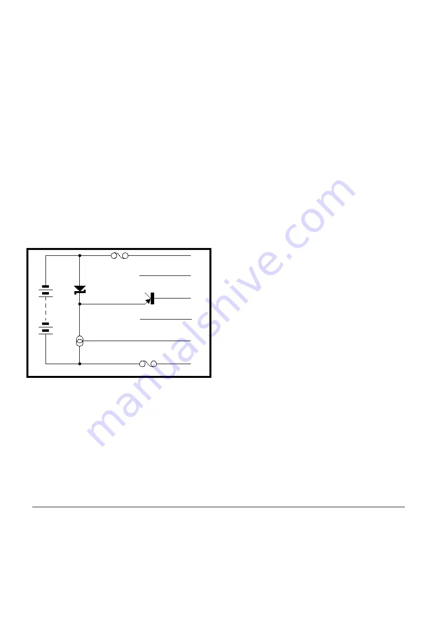
An understanding of the internal powering
arrangements may help you find problems (both in
the controller and in your wiring).
Connecting the ignition to battery positive turns on a
current source (about 30mA) which powers all the
internal circuitry, using a 9v1 zener diode as a
regulator. This system is very reliable as it tends to
fail safe: zeners when overloaded usually fail short
circuit, which removes all internal power.
The 9v1 line is fed to the top of the pot via a
transistor (which detects open circuit pot wiring), so
when the internal supply is powered up you can
measure about 8.5v across the pot. Operating the pot
will, then, change the blue wire to pin E from 0v to
8.5v, depending on the pot setting.
Main capacitor:
Be aware that certain uses of the controller can cause
this to heat, particularly if the battery leads are long.
The main capacitor may get warm, but should not be
allowed to remain hot to touch for too long. Heating
will shorten the life of this capacitor and, if
excessive, can cause it to vent. When it vents, the
liquid electrolyte inside boils and vents. Although the
capacitor failing does not do any direct damage (the
controller simply looses power) the venting capacitor
can expel hot electrolyte: if this gets on to the wrong
9v1 zener
current source
b
ignition
reverse
pot top
pot wiper
pot zero (batty -)
pot fault detector
A
B
C
D
E
F
F2
F3
15: Common faults


