4ms Dual Looping Delay User Manual Download Page 12

Special Modes

Firmware Version

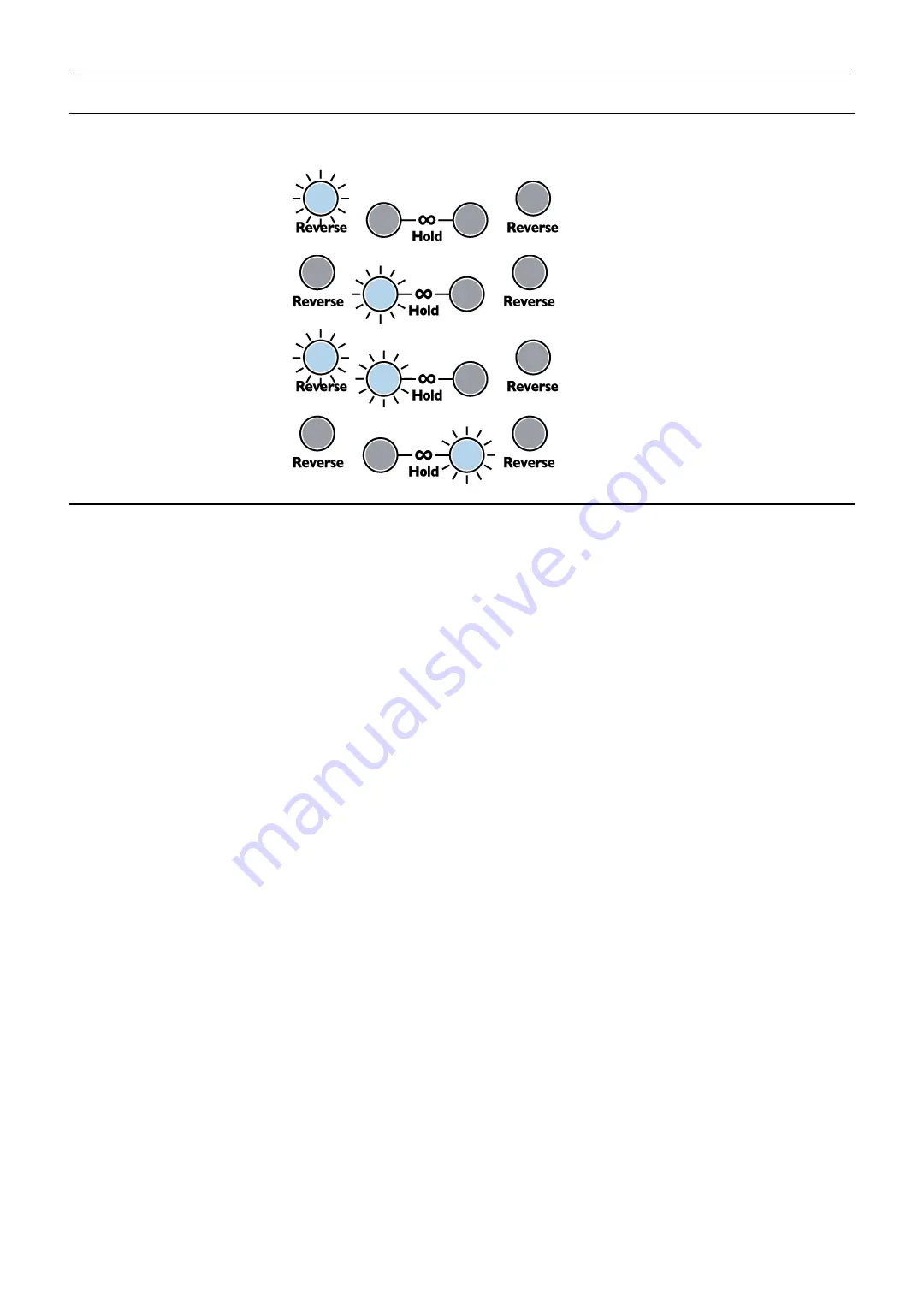
To view the firmware version, enter 

System Settings Mode

 by flipping both 

Time

 switches up (to +16) and hold down all five 

buttons until all the buttons and both Loop lights turn on brightly (about 8 seconds). Then, release the five buttons and look at 
which buttons are lit up. Briefly press and release all five buttons again to exit System Mode

Firmware v1

(pre-release)

Firmware v2

(Released early May 2016)

Firmware v3

(Released late May 2016)

Firmware v4

(Released June 2, 2016) 

System Settings Mode

System Settings Mode allows you to change the way some features of the DLD behave. For most users, these are not 
necessary to modify, but advanced users may wish to explore. 

It's recommended that new users get familiar with the DLD 

operation using default system settings before making changes!

To enter System Settings Mode, flip both 

Time

 switches up and hold down all five buttons for about 8 seconds until both Loop 

lights and all five buttons turn on brightly. Release the buttons. You are now in System Settings Mode. 

Proceed carefully and 

take the time to understand what you are doing


before pressing any buttons, turning any knobs, or flipping any 

switches

. Changing a System Setting without realizing what you changed can cause confusion. You can always do a Factory 

Reset if you want to revert to safe settings (see Factory Reset section below). You also can exit System Settings mode 
without changing anything by briefly tapping all five buttons when the Time switches are both up.

The 

Time

 switches are used to determine what parameters you are editing. The buttons and knobs are used to edit these 

parameters

• Time A up + Time B down: Clock Output Trigger/Gate selection and LED brightness

The clock output jacks can output gates or triggers (22ms pulse width). In this mode, the loop lights and Ping light will each 
blink once in sequence. A short flicker means the associated jack is in trigger mode, and a longer blink means it's in gate 
mode. The associated button will also be lit to indicate gate mode, or unlit to indicate trigger mode.

Gate/Trigger output for 

Loop A

 jack: Tap 

Reverse A

 to toggle mode

Gate/Trigger output for 

Loop B

 jack: Tap 

Reverse B

 to toggle mode

Gate/Trigger output for main 

Clock Out

 jack: Tap 

Infinite Hold A

 to toggle mode

The red and blue Loop LEDs can be dimmed:

LED brightness (red and blue only): Hold 

Infinite Hold B

 while turning the 

Feedback A

 knob (In firmware v3 and 

earlier, it's not necessary to press 

Infinite Hold B

)

• Time A up + Time B center: Auto Mute, Soft Clipping, and Mix CV

Auto Mute

 is a noise gate that silences the input when a signal less than 5mVpp is detected on any input. This prevents 

runaway feedback if 

Feedback

 is turned up and the DLD is allowed to run for a long time with no input signal. In most cases, 

it is not necessary to turn off the Auto-mute, since a 5mVpp signal is extremely quiet.

Soft Clipping

 enables limiting (compression) when the output signal exceeds 75% of the clipping point. Below this point, the 

signal is unaffected. This saturation distortion sounds is often more pleasing to hear versus harsh clipping. In most cases, it is 
not necessary to disable soft clipping.

Mix CV

, when enabled, re-assigns the 

Delay Feed CV

 jack to control the 

Mix

 (

Dry/Wet)

 amount

Auto Mute

: Tap 

Reverse A

 to toggle Auto Mute on and off. When the light is on, Auto Mute is enabled.

Soft Clipping

: Tap 

Reverse B

 to toggle Soft Clipping on and off. When the light is on, Soft Clipping is enabled.

Mix A CV

: Tap 

Infinite Hold A

 to toggle the Delay Feed A CV jack between controlling Mix and Delay Feed. When the 

light is on, the jack controls Mix.

Mix B CV

: Tap 

Infinite Hold B

 to toggle the Delay Feed B CV jack between controlling Mix and Delay Feed. When the 

light is on, the jack controls Mix.

12

Summary of Contents for Dual Looping Delay

Page 1: ...essly with modular timebase and sequencing devices such as the 4ms Quad Clock Distributor QCD etc Two channels each with nearly 3 minutes maximum delay loop time at 48kHz 16 bit option for 24 bit Extremely quiet low noise low jitter design Stereo cascading or dual independent mono use Delay and loop time is sync able to a clock or a division or multiplication of a clock Infinite Hold mode for loop...

Page 2: ...utput Buffer can be cleared with a button press 20HP Eurorack module Controls and jacks Channels A and B are identical and separate except for the common clock and audio normalizations Controls Ping button Tap a tempo to set the base clock one beat Base time can also be set by an external clock Time knob per channel sets the loop time in number of beats Ranges from 1 to 16 Time switch per channel ...

Page 3: ...g jack The VCO should be in the low or mid audio range less than 2kHz 250 500Hz is ideal Feed a signal into the In jack noise works well so do triggers 10V triggers will resonant more 5V triggers are barely enough to trigger the resonance Use the Time switch and knob to set the Pitch Feedback sets the resonance which determines the amplitude of the pitch and Delay Feed effects the level and resona...

Page 4: ...y the Ping button or jack Each channel can multiply divide or add to the base time by using the Time knob switch and CV Anytime the base time is changed by tapping the Ping button or changing the external clock both channels will instantly change tempo while maintaining the same ratio to each other Channel normalizations The main In A jack feeds into the switch tab of the main In B jack Therefore ...

Page 5: ...de in portions of the signal onto the loop The knob and CV jack are added together and have a maximum combined value of 100 Negative voltage on the CV jack is ignored Note that in Inf Hold mode Delay Feed has no effect since there is no recording Feedback Also known as regeneration echo amount and other names feedback is a common feature on delay effects Feedback is the amount of signal read from ...

Page 6: ...ily The loop is more dynamic and mutable versus when Infinite Hold is on the loop is more static and immutable Reverse Reverse reverses the direction that memory is read and written Pressing the Reverse button toggles Reverse on off when the button is released If you turn a knob while Reverse is held down the Reverse action will be cancelled this is because holding a button while turning a knob is...

Page 7: ...oll back very far even more quickly than Tip 1 change the Time parameter to very long perhaps flip the time switch up to 16 Since turning Feedback Infinite Hold scrolls by one loop size making the loop size enormous lets you scroll by enormous amounts with just one knob twist You can scroll back a maximum of 2 minutes 54 seconds Tip 3 Set Time to a very short period and window around a loop with C...

Page 8: ...atch a manual CV source into the Delay Feed B CV jack It can be a Pressure Points or an FSR pressure output or perhaps an envelope output that s triggered manually When you press on the Pressure Points or FSR you will bring up the Delay Feed parameter which causes audio to be recorded onto the loop Since Feedback is at 100 the loop is infinite and everything you lay down will remain but take care ...

Page 9: ...k and use the Mix A knob to blend between the dry signal and Channel A s delay Reverb y echo room Patch as shown on the left Try setting one channel s Time to a fast delay such as 1 with the Time switch flipped to 1 8 Set the other Time to a slow delay such as 8 Set both channel s feedback amounts to around 75 90 Take the output from Out B Tap a very fast tempo as fast as your finger will go While...

Page 10: ...ts Feedback with External Processing The classic use of Send and Return ports in a time delay processor is to provide a side chain for modifying the delayed signal before it is returned to the input mix Probably the most classic application of this kind of side chain processing is a simple low pass filter in the feedback path This causes succeeding repeats to soften with less high frequency conten...

Page 11: ...e reset it back to the start and tap Reverse A button to reset The Hold A button should light up Play the file from the beginning again 6 If the file loads successfully the DLD will immediately start running In some cases you may need to do a Factory Reset see Factory Reset section Estimated late June 2016 the open source licensed source files in C for compiling with gcc arm can be found at https ...

Page 12: ...pulse width In this mode the loop lights and Ping light will each blink once in sequence A short flicker means the associated jack is in trigger mode and a longer blink means it s in gate mode The associated button will also be lit to indicate gate mode or unlit to indicate trigger mode Gate Trigger output for Loop A jack Tap Reverse A to toggle mode Gate Trigger output for Loop B jack Tap Reverse...

Page 13: ...switches up hold down all five buttons for 8 seconds Calibration Mode Your DLD has been calibrated at the factory and should not need re calibration Hardware hackers should be aware that the calibration data is stored in FLASH memory at 0x08004000 to 0x08007FFF If this sector is erased the DLD will automatically re calibrate itself on boot Make sure nothing is plugged into any CV jacks the first t...

Page 14: ... disabled Clock outputs Main Loop A Loop B 0V to 8 2V 2 4µs maximum jitter i e 0 001 at 120 BPM Rise or Fall time 1µs Pulse Width Trigger mode 22ms Gate mode 50 square wave At clock speeds faster than 22Hz the clock output becomes 50 duty cycle Sampling 24 bit sample at 48kHz 32 bit processing 16 bit storage in RAM 256Mbit nonvolatile SDRAM chip for a maximum of 2 minutes 54 seconds per channel 6m...

Page 15: ...t Gate Triggers for clock outputs Dim the loop LEDs Re assign Delay Feed CV jacks to Mix Enable disable auto mute and soft clipping Adjust 1V oct tracking No clicking when doing a Reverse or exiting Infinite Hold mode Exiting Infinite mode quickly crossfades to play from the beginning of the loop Fixed the loop lights so they display better at high speeds 15 ...

Page 16: ...16 ...

Reviews: