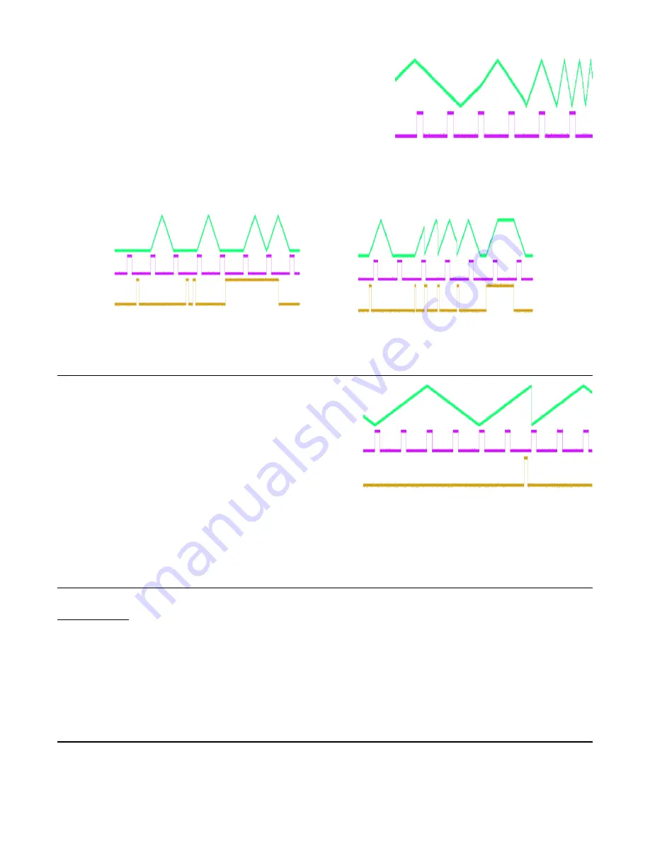
re-sync to the ping clock. Notice how the envelopes do not
necessarily start or end on a ping clock.
Using the Trigger Jack in Sync and Async Mode
When the
Trigger
jack is configured as Quantize and it receives
a trigger, the module will wait for the next divided/multiplied ping
clock before staring the envelope. See Figure 6.
When the
Trigger
jack is set to Async Trigger or Async Gate, an
envelope will begin immediately upon receiving a trigger,
regardless of whether the ping clock is firing at the same
moment. See Figure 7.
Quantize Trigger Re-Phasing
In
Sync
mode, when
Div/Mult
is set to dividing and the
Cycle
button is on, firing a trigger into the
Trigger
jack
configured as Quantize will re-start (re-phase) the
envelope on the next incoming ping clock. For example,
if
Div/Mult
is set to /4 then the ping clock represents
quarter notes, and we could count measures as
1-2-3-4-1-2-3-4 etc. The envelope starts on the “1”,
reaches its peak on the “3” and finishes just as the next
“1” occurs. If we were to fire a trigger into the Quantize
Trigger
jack somewhere in between the “2” and “3”,
then the envelope would re-phase so that it starts on the
“3”. See Figure 8.
This can be useful for multi-phase outputs (e.g. Quadrature patch).
Tap Clock Output
The
EOF
jack can be configured to output a tap tempo clock. This is done in System Mode (see
System Mode section). When configured as Tap Clock, whatever tempo you tap on the
Ping
jack will
be steadily output on the
EOF
jack. Unlike configuring the
EOF
jack as End-of-Rise, End-of-Fall, or
Half-Rise, the
Div/Mult
parameter will not affect the tempo being output on this jack. More importantly,
the tempo you tapped will continue to be output even if you are clocking the
Mini PEG
with an external
clock at a different tempo.
This feature allows you to use the
Ping
button and
EOF
jack as a semi-independent tap tempo sub-
module: tapping the
Ping
button will only change the tempo on the
EOF
jack and not the tempo of the
envelopes.
Bus Clock
Clock Bus is a 1:1 clock that runs along the gate pin of the Eurorack power bus. This feature allows for
a compatible module to send a clock signal over the power bus, and for one or more modules to
synchronize to this clock. The
MiniPEG
,
DLD
, and
QCD
from 4ms are all capable of sending and
Page of
8
12
Figure 5: Changing Div/Mult in Async Mode
Figure 7: Async Gate jack (gold).
Figure 6: Quantized Trigger jack (gold)
Figure 8: Re-phasing a /4 envelope.
1
1
1
2
3
4
2
3
4


