15 of 31
Interlock Wiring
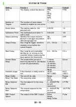
When the interlock setting is set to “USED” the Interlock must be connected for
outputs to trigger. When the Interlock is connected and the start-up delay has elapsed,
the symbol RUN is displayed at the top of the runtime screen.
When the interlock setting is set to “NOT USED” the state of the interlock does not
matter.
INSTALLATION
The Speed Relay should be wired as show in the connection diagrams in Electrical
Setup.
Speed Relay Mounted on 35mm DIN rail
The Speed Relay should be mounted on a 35mm DIN rail in suitable enclosure of
protection rating IP40 or above. The enclosure door should be kept locked when the
system is in operation.
Use a small flathead screwdriver to lower the hook on the rear of the Speed Relay to
install or remove the device.
Summary of Contents for USR1V4
Page 3: ......
Page 10: ...10 of 31 APPROVALS In Process DIMENSIONS ALL DIMENSIONS IN MM...
Page 29: ...29 of 31 NOTES...


