


PS5010G-2GS-8PoE User Manual
5
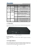
1.3 External Component Description
1.3.1 Front Panel
The front panel of the Switch consists of 8 x 10/100/1000Mbps RJ-45 ports, 1x
CONSOLE port, 2 x SFP ports, 1 x RESET button and a series of LED indicators as
shown as below.
Figure 1 - Front Panel
10/100/1000Mbps RJ-45 ports (1~8):
Designed to connect to the device with a bandwidth of 10Mbps, 100Mbps or 1000Mbps.
Each has a corresponding 10/100/1000Mbps LED.
CONSOLE port (CONSOLE):
Designed to connect with the serial port of a computer or terminal for monitoring and
configuring the Switch.
SFP ports (SFP1, SFP2):
Designed to install the SFP module and connect to the device with a bandwidth of
1000Mbps. Each has a corresponding 1000Mbps LED.
RESET button (RESET):
Keep the device powered on and push a paper clip into the hole.
Press down the button for 2 seconds to reboot the Switch, Press down the button for 5
seconds to restore the Switch to its original factory default settings.
LED indicators:
The LED Indicators will allow you to monitor, diagnose and troubleshoot any potential
problem with the Switch, connection or attached devices.
Figure 2 - LED Indicators
The following chart shows the LED indicators of the Switch along with explanation of each
indicator.


