

Check whether the DIN-Rail mounting kit that
Step 1
comes with the device is installed firmly.
Insert the bottom of DIN-Rail mounting kit (one side
Step 2
with spring support) into DIN-Rail, and then insert
the top into DIN-Rail.
Tips:
Insert a little to the bottom, lift upward and then insert
to the top.
Check and confirm the product is firmly installed on
Step 3
DIN-Rail, and then mounting ends.
【
Disassembling DIN-Rail
】
Power off the device.
Step 1
After lift the device upward slightly, first shift out the
Step 2
top of DIN-Rail mounting kit, and then shift out the
bottom of DIN-Rail, disassembling ends.
Attention before power on:
Power ON operation: first connect power line to the
connection terminal of device power supply, and then
power on.
Power OFF operation: first unpin the power plug, and
then remove the power line, please note the operation
order above.
【
Power Supply Connection
】
DC power supply
The product provides 4 pins power
supply input terminal blocks and two
independent
DC
power
supply
systems of PWR1 and PWR2. The
power supply supports anti-reverse connection. Power supply
range: 48VDC.
【
Relay Connection
】
Relay terminal blocks are a pair of normally
open contacts in the alarm relay of the device.
They are open circuit in the status of normal no
alarm, and closed when any warning message occurs. For
example: they are closed and send out alarm when power off.
The product supports 1 relay warning message output, and
warning messages output of the DC power supply or network
abnormal alarm output. It can be connected to alarm indicator,
alarm buzzer, or other switching value collecting devices for
timely warning operating staffs when the warning message
occurs.
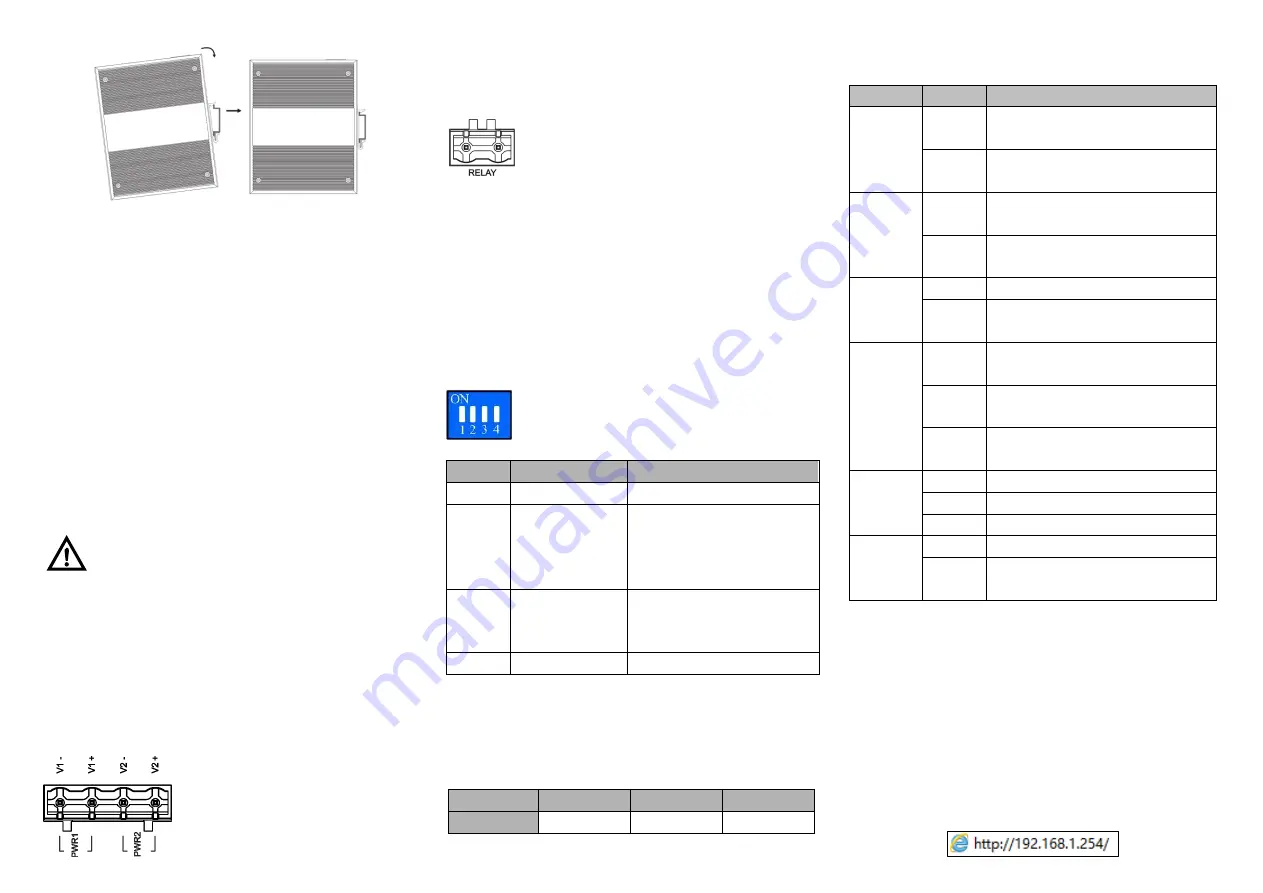
【
DIP Switch Settings
】
The product provides 4 pins DIP switch for
function settings, where "ON" is the enable valid
terminal.
DIP switch definitions as follows:
DIP
Definition
Operation
1
Reserved
-
2
Restore factory
defaults
Set the DIP switch to ON, the
device will automatically
restore factory defaults, and
then turn off the DIP switch.
3
Upgrade
Set the DIP switch to ON, the
device will be upgraded, and
then turn off the DIP switch.
4
Reserved
-
【
Console Port Connection
】
The device provides 1 channel procedure debugging port
based on serial port, and can manage the CLI command line
of the device after connected to PC. The interface adopts
RJ45 port, the RJ45 pins definition as follows:
Pin No.
2
3
5
Definition
TXD
RXD
GND
【
Checking LED Indicator
】
The function of each LED is described in the table as below:
LED
Status
Description
P1
ON
PWR1 is connected and running
normally
OFF
PWR1 is disconnected and running
abnormally.
P2
ON
PWR2 is connected and running
normally
OFF
PWR2 is disconnected and running
abnormally
ALM
ON
Power supply and port link alarm
OFF
Power supply and port link without
alarm
RUN
ON
The device is powering on or
abnormal.
OFF
The device is powered off or
abnormal.
Blinking
Blink once per second, the device is
running well.
Link/ACT
(1-4/G1-
G2)
ON
Ethernet port connection is active.
Blinking
Data transmitted
OFF
Ethernet port connection is inactive.
PoE+
(1-4)
ON
PoE port is powering other devices.
OFF
PoE port is not connected or PoE
function is not enabled.
【
Logging in to WEB Interface
】
This device supports WEB management and configuration.
Computer can access the device via Ethernet interface. The
way of logging in to device
’s configuration interface via IE
browser is shown as below:
Configure the IP addresses of computer and the
Step 1
device to the same network segment, and the
network between them can be mutually accessed.
Enter device
’s IP address in the address bar of the
Step 2
computer browser.


