


Note before installation:
Don't place or install the device in area near water or
moist, keep the relative humidity of the device
surrounding between 5%~95% without condensation.
Before power on, first confirm the supported power
supply specification to avoid over-voltage damaging the
device.
The device surface temperature is high after running;
please don't directly contact to avoid scalding.
【
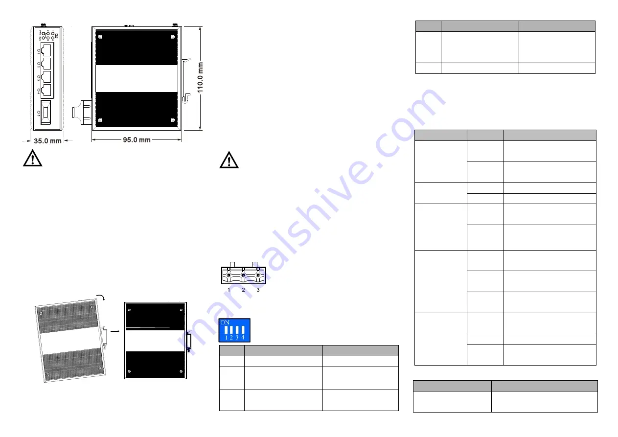
DIN-Rail Mounting
】
For convenient usage in industrial environments, the product
adopts 35mm DIN-Rail mounting, mounting steps as below:
Check if the DIN-Rail mounting kit is installed firmly.
Step 1
Insert the bottom of DIN-Rail mounting kit (one side
Step 2
with spring support) into DIN-Rail, and then insert
the top into DIN-Rail.
Tips:
Insert a little to the bottom, lift upward and then insert
to the top.
Check and confirm the product is firmly installed on
Step 3
DIN-Rail, then mounting ends.
【
Disassembling DIN-Rail
】
Device power off.
Step 1
After lift the device upward slightly, first shift out the
Step 2
top of DIN-Rail mounting kit, then shift out the
bottom of DIN-Rail, disassembling ends.
Note before power on:
Power ON operation: first connect power line to the
connection terminal of device power supply, then power
on.
Power OFF operation: first unpin the power plug, then
remove the power line, please note the operation order
above.
【
Power Supply Connection
】
DC power supply
The series devices provide 3 pins industrial
terminal blocks (1, 2, 3), among which 1
and 3 are 45
~
55VDC power supply input.
It supports anti-reverse functions.
【
DIP Switch Setting
】
Provide 4-bits DIP switch for function setting,
where "ON" is enable valid terminal.
DIP switch defines as follow:
No.
Definition
Operation
1
Flow control
Set the switch to ON
2
100M
copper
port
specified 10M
Set the switch to ON
3
VLAN (port5 can
communicate with port
Set the switch to ON
No.
Definition
Operation
1-4, port 1-4
can’t
communicate with each
other)
4
Reserved
-
【
Checking LED Indicator
】
This device provides LED indicator for monitoring the work
status of device, which has simplified the troubleshooting
process comprehensively. The function of each LED is
described in the table as below:
LED
Status
Description
PWR
ON
PWR is connected and
running normally
OFF
PWR is disconnected or
running abnormally
RUN
ON/OFF
The device is abnormal
Blinking
System is running normally
PoE port
power supply
status indicator
(1-4)
ON
PoE port is powering other
device normally
OFF
PoE port is not powering
other device
PoE port link
status indicator
(1-4)
ON
PoE port has established
valid network connection
Blinking
PoE port is in an active
network status
OFF
PoE port has not established
valid network connection
Link/ACT (5)
ON
Ethernet port connection is
active.
Blinking
Data transmitted
OFF
Ethernet port connection is
inactive.
【
Specification
】
Panel
100M fiber port
100Base-FX, optional SC/ST/FC
interface


