


Notice:
Don't place or install the device in area near water or
moist, keep the relative humidity of the device
surrounding between 5%~95% without condensation.
Before power on, first confirm the supported power
supply specification to avoid over-voltage damaging the
device.
The device surface temperature is high after running;
please don't directly contact to avoid scalding.
【
Power Supply Connection
】
DC power supply
This device provides 4-pin power supply
terminal blocks and 2 independent DC
power supply systems, PWR1 and PWR2.
This power supply has non-polarity and
reverse connection protection.
Power supply range: 9 ~ 70VDC
Notice
:
Power ON operation: first connect power line to the
connection terminal of device power supply, then power
on.
Power OFF operation: first unpin the power plug, then
remove the power line, please note the operation order
above.
【
Serial Port Connection
】
3IN1 serial port
This device provides 3IN1 serial port and
supports RS232, RS485 and RS422 at
the same time. The interface type is
terminal blocks and its pin definitions are
shown in the table below:
PIN
1
2
3
4
5
RS-232
—
TXD
GND
—
RXD
RS-485
D+
D-
GND
—
—
RS-422
T+
T-
GND
R+
R-
【
Checking LED Indicator
】
The device provides LED indicators to monitor its operating
status, which has simplified the overall troubleshooting
process. The function of each LED is described in the table
below:
LED
Status Description
P1
ON
Power supply P1 is connected
and running normally
OFF
Power supply
P1
is
disconnected and running
abnormally
P2
ON
Power supply P2 is connected
and running normally
OFF
Power supply
P2
is
disconnected and running
abnormally
RUN
OFF
Device is not powered on or in
an abnormal state
Blinking
Blinks once per second, device
runs normally
1-3
ON
Port has established valid
connection
Blinking Data is being transmitted
OFF
Port hasn’t established valid
connection
COM
ON
Data is being transmitted
OFF
No data is being transmitted or
port is in an abnormal state
【
Logging in to WEB Interface
】
This device supports WEB management and configuration.
Computer can access the device via Ethernet interface. The
way of logging in to device’s configuration interface via IE
browser is shown as below:
Step 3
Configure the IP addresses of computer and the
device to the same network segment, and the
network between them can be mutually accessed.
Step 4
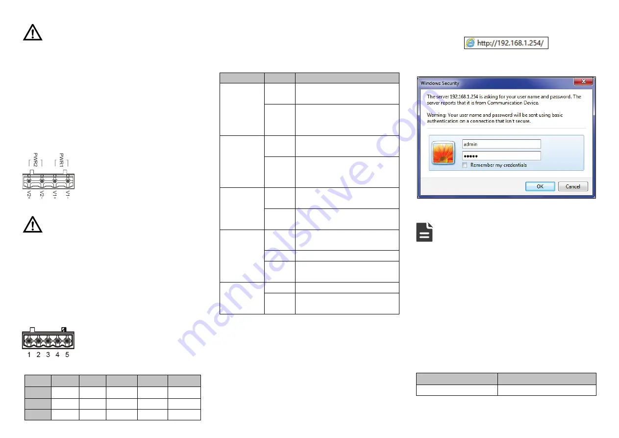
Enter device’s IP address in the address bar of the
computer browser.
Step 5
Enter device’s username and password in the login
window as shown below.
Step 6
Click “OK” button to login to the WEB interface of
the device.
Note:
The default IP address of the device is “192.168.1.254”.
The default username and password of the device is
“admin”.
If the username or password is lost, user can restore it to
factory settings via device DIP switch or management
software; all modified configurations will be cleared
after restoring to factory settings, so please backup
configuration file in advance.
Please refer to user manual for specific configuration
method of logging in to WEB interface and other
configurations about network management function.
【
Specification
】
Panel
100M fiber port
100 Base-FX